background image

1-2  

TO THE INSTALLER

Model C300

To the Installer 

CAUTION!

 This unit must be installed on a 

level surface to avoid the hazard of tipping. Extreme care 

should be taken in moving this unit for any reason. Two 

or more persons are required to safely move this unit. 

Failure to comply may result in personal injury or damage 

to the unit.

The authorized installer should inspect the unit for 

damage and promptly report any damage to the local 

authorized Taylor distributor.

This unit is made using USA sizes of hardware. All metric 

conversions are approximate and vary in size.

Water-Cooled Refrigeration Units

(Water-Cooled Units Only)

On the back of the unit, two additional 3/8 in. (9.5 mm) 

F.P.T. water connections for condenser inlet and outlet 

have been provided for easy hookup. 3/8 in. (9.5 mm) 

inside diameter water lines should be connected to the 

machine. Flexible lines are recommended if local codes 

permit. Failure to use adequately sized water lines may 

cause the unit to go on high head pressure and shut 

down.

Do not

 install a hand shutoff valve on the out line. Water- 

cooled units are counter flow and the water should flow in 

this order: first through the automatic water valve; 

second, through the inlet located at the bottom of the 

condenser; third, through the outlet fitting located at the 

top of the condenser 

to an open trap drain.

Important! 

Water pressures are pre-set at the factory. 

Do not 

adjust the water pressure

Improper water adjust-

ments may cause operation discrepancies.

IMPORTANT! 

A backflow prevention device is 

required on the incoming water connection side. Please 

see the applicable national, state, and local codes for 

determining the proper configuration.

Water Connections

An adequate cold water supply must be provided with a 

hand shutoff valve. On the back of the unit, two 3/8 in. 

(9.5 mm) male flare water connections have been 

provided for easy hookup. A flexible line is recommended, 

if local codes permit. A minimum of 25 psi. (172 kPa) 

water pressure is required to avoid having the unit cut out 

the low water pressure switch. A booster pump must be 

provided if this pressure is not available. 

Note:

Water lines beyond 200 ft. (61 m) require 1/2 in. 

(13 mm) water lines.

IMPORTANT! 

Install potable water connection 

with a water filter and adequate backflow protection to 

comply with applicable national, state, and local codes. 

Water temperature is not to exceed 125°F (51°C). Water 

pressure to the machine must be 55 to100 psi 

(379 to 690 kPa).

It is always a good practice to have a filter system to 

improve the quality of the water and to avoid clogging the 

operating components.
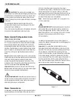
Important! 

The water filter (064422-SER) must be 

thoroughly flushed with water before connecting it to the 

machine. This removes any loose particles present from 

the manufacture of the filter that could clog the flow 

control. To flush the filter, connect the inlet end of the filter 

to the water supply. Position the outlet end of the filter 

over an empty pail. Open the water supply. Allow water to 

flow through the filter until the water exiting the filter is 

clear. Close the water supply. Attach the outlet end of the 

filter to the machine. Reopen the water supply.
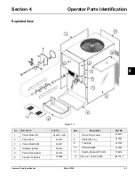
Figure 1-1

!

!

Содержание C300 NP

Страница 1: ...OPERATOR S MANUAL Model C300 Slush Freezer 9 26 08 Original Publication Updated 1 8 2019 Original Operating Instructions 055072 M...

Страница 2: ..._ Cycle__________ Phase__________________________________ Maximum Fuse Size ______________________________________________________ A Minimum Wire Ampacity _____________________________________________...

Страница 3: ...ressor Warranty Disclaimer 2 2 Section 3 Safety Section 4 Operator Parts Identification Exploded View 4 1 Beater Door Assembly 4 2 Accessories 4 3 Section 5 User Interface Control Switch 5 1 Liquid Cr...

Страница 4: ...Cylinder 6 10 Rinsing 6 11 Cleaning 6 11 Disassembly 6 12 Brush Cleaning 6 12 Section 7 Operator Checklist During Cleaning and Sanitizing 7 1 Troubleshooting Bacterial Count 7 1 Regular Maintenance Ch...

Страница 5: ...R The main power supply s to the unit must be disconnected prior to performing any installation maintenance or repairs Failure to follow this instruction may result in personal injury or death from el...

Страница 6: ...ncies IMPORTANT A backflow prevention device is required on the incoming water connection side Please see the applicable national state and local codes for determining the proper configuration Water C...

Страница 7: ...pairs or maintenance Machines that are permanently connected to fixed wiring and for which leakage currents may exceed 10 mA particularly when disconnected or not used for long periods or during initi...

Страница 8: ...a hermetically sealed circuit or within foam insulation This unit s type of gas quantity Global Warming Potential GWP and CO2 tonnes equivalent information is recorded on the unit s data label The re...

Страница 9: ...anty is valid only if the parts are authorized Taylor parts purchased from the local authorized Taylor distributor and only if all required service work is provided by an authorized Taylor service tec...

Страница 10: ...fact known to any technician he employs It should also be noted that Taylor does not warrant the refrigerant used in its equipment For example if the refrigerant is lost during the course of ordinary...

Страница 11: ...ounding lug is provided with this unit Some countries require the grounding lug to be properly attached to the rear of the frame by the authorized installer The installation location is marked by the...

Страница 12: ...This machine must be placed on a level surface Extreme care should be taken when moving the for any reason Two or more persons are required to safely move this machine Failure to comply may result in...

Страница 13: ...minimum of 3 in 76 mm air clearance on both sides of the machine is required It is recommended to place the rear of the machine against the wall to prevent the recirculation of warm air Failure to fol...

Страница 14: ...3 4 SAFETY Model C300 Safety 3 Notes...

Страница 15: ...on Part No 1 Panel Side Left X54676 SER 2 Panel Rear 054672 3 Panel Side Right 054671 4 Display Lighted 069143 5 Panel Front Upper 069142 6 Panel Front Shell 054668 Item Description Part No 7 Panel Fr...

Страница 16: ...Door 039321 9 Slide Handle Door FCB 046193 BLA 10 Screw 10 32X3 8 Phil 053869 11 O ring 9 32 OD X 1 16 Wall 25 to Bag 029751 12 Plug Prime Slush 039568 13 O ring 1 129 ODX 989ID X 070W 25 to Bag 03921...

Страница 17: ...055492 100 2 oz packs or Kay 5 part no 041082 200 packs 1 3 4 5 2d 2c 2b 2a 2 Item Description Part No 1 Pail 10 QT 013163 2 Brush A Package X64275 2a Brush Mix Pump Body 3 x7 023316 2b Brush Double...

Страница 18: ...4 4 OPERATOR PARTS IDENTIFICATION Model C300 Operator Parts Identification 4 Notes...

Страница 19: ...up CO2 and water being supplied to the freezer If an error in the machine operation occurs a warning tone will sound and the word FAULT will flash on the third line of the display Operational Mode Dis...

Страница 20: ...rator menu selections except for Current Conditions the display will return to the system mode screen 60 seconds after the last key press The Current Conditions screen will be displayed until manually...

Страница 21: ...he warning tone will clear CO2 PRESSURE LOW When the CO2 out indicator displays a lack of CO2 a 60 second internal timer will start If the CO2 is not replenished at the end of the 60 seconds both free...

Страница 22: ...press the MENU SEL key once To return to the Main Screen use the AUTO key to cycle to menu item A then press the MENU SEL key Screen C SET CLOCK Use the AUTO and OFF keys to place the cursor under the...

Страница 23: ...e fourth feature will display the POWER SAVER MODE with a status of OFF REST or STANDBY If the POWER SAVER MODE is OFF the following screen will be displayed If a Power Saver mode is programmed one of...

Страница 24: ...The fault description is listed on the third line of the fault page Press the AUTO key to move to the next screen The next screen will indicate when the fault was satisfied Press the MENU SEL key to r...

Страница 25: ...a lack of water being supplied to the freezer In addition the product light will illuminate and a warning tone will sound This will continue until the proper amount of water is supplied to the freeze...

Страница 26: ...5 8 USER INTERFACE Model C300 User Interface 5 Notes...

Страница 27: ...ill flow from the flow control into the freezing cylinder CO2 is supplied after the flow control to carbonate the product and aid in dispensing We begin our instructions at the point where the parts a...

Страница 28: ...coupling without binding Remove any excess lubricant from the seal Figure 6 4 5 Install the beater assembly First check the scraper blades for any nicks or signs of wear If any nicks are present or if...

Страница 29: ...ings into the grooves on the draw valve Lubricate the O rings and the valve as illustrated below Figure 6 8 8 Insert the draw valve into the freezer door spout from the front of the unit The valve is...

Страница 30: ...in through the mounting adaptor and into the ADA handle Mount the assembled ADA handle onto the pivot pin Figure 6 12 12 Secure the assembly with the screw Figure 6 13 13 Insert the spring into the fr...

Страница 31: ...Install the four handscrews on the studs and finger tighten them equally in a criss cross pattern to insure that the door is snug Important Do not over tighten the handscrews Figure 6 20 20 Repeat the...

Страница 32: ...e 6 22 4 Connect the syrup line to the syrup line connector that was cut from the syrup bag Figure 6 23 5 With the bag connector attached to the syrup line place the syrup line into the pail of saniti...

Страница 33: ...olution purges out of the relief valve at the top of the mix tank and begins draining into the front drip tray Press the OFF key 11 Press the BEATER key Agitate the solution in the freezing cylinders...

Страница 34: ...quality and taste of the product Brixing should be done before priming the freezer and when a change in syrup flavor has been made 7 Drain the product from the syrup sampling valve into a cup Close t...

Страница 35: ...llecting brix samples The center position shuts off the product flow The up position directs the flow of product to the freezing cylinder 12 Place a pail beneath the door spout Open the draw valve and...

Страница 36: ...g pails Necessary brushes provided with freezer Cleaner Single service towels Draining Product from the Freezing Cylinder 1 With a pail beneath the door spout press the BEATER key This will allow the...

Страница 37: ...ed 2 Place the syrup line with the old syrup connector into the pail of cleaner 3 To place the left freezing cylinder in the Sanitize mode press the MENU SEL key Move the cursor by pressing the AUTO k...

Страница 38: ...ylinder 3 Remove the following parts from the freezer and take them to the sink for brush cleaning Hand screws Freezer doors Baffle assemblies Beater assemblies and scraper blades Drive shafts Hopper...

Страница 39: ...d front bearings from freezer doors Discard all O rings and replace them with new ones Note To remove O rings use a single service towel to grasp the O ring and apply pressure in an upward direction u...

Страница 40: ...6 14 OPERATING PROCEDURES Model C300 Operating Procedures 6 Notes...

Страница 41: ...intenance Checks Replace scraper blades that are nicked damaged or worn down Before installing the beater make sure that the scraper blades are properly attached over the pins Check the rear shell bea...

Страница 42: ...7 2 OPERATOR CHECKLIST Model C300 Operator Checklist 7 Notes...

Страница 43: ...circuit breaker is off b Replace the fuse or turn the breaker on c Beater motor is out on overload Check fault description screen c Allow the motor to cool Press the AUTO key Call a service technician...

Страница 44: ...roperly 6 3 b Wrong type lubricant on draw valve O rings b Use food grade lubricant example Taylor Lube HP 6 1 c Worn or missing draw valve O rings c Replace or install O rings on draw valve 6 3 9 1 1...

Страница 45: ...e X Drive Shaft Seal X Drive Shaft O ring X Freezer Door Gasket X Draw Valve O ring X Front Bearing X Prime Plug O ring X Black Bristle Brush 1 x 2 Inspect and replace if necessary Minimum Double Ende...

Страница 46: ...9 2 Model C300 Parts Replacement Schedule PARTS REPLACEMENT SCHEDULE 9 Notes...

Страница 47: ...number Proof of purchase may be required at time of service 2 This limited warranty is valid only if the Product is installed and all required service work on the Product is performed by an authorize...

Страница 48: ...ulting from the use of any refrigerant other than that specified on the Product s data label will void this limited warranty 13 Any cost to replace refill or dispose of refrigerant including the cost...

Страница 49: ...red at time of service 2 This limited warranty is valid only if the Part is installed and all required service work in connection with the Part is performed by an authorized Taylor distributor or serv...

Страница 50: ...arranty service work promptly upon arrival 9 Failure damage or repairs due to faulty installation misapplication abuse no or improper servicing unauthorized alteration or improper operation or use as...

Страница 51: ...NCIDENTAL DAMAGES INCLUDING CLAIMS FOR LOST SALES LOST PROFITS PRODUCT LOSS PROPERTY DAMAGES OR SERVICE EXPENSES ARE EXPRESSLY EXCLUDED THE EXPRESS WARRANTIES MADE IN THIS LIMITED WARRANTY MAY NOT BE...

Страница 52: ...LIMITED WARRANTY ON PARTS 11 4 Model C300 Limited Warranty on Parts 11 Notes...

Отзывы: