


OPERATING PROCEDURES
6-3
Model C300
Operating Procedures
6
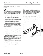
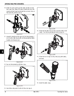
Figure 6-6
Note:
The scraper blades on the beater assembly
should be in the 6 and 12 o’clock positions. This will
enable freezer door installation.
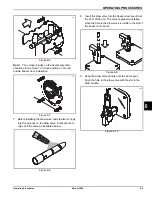
Figure 6-7
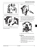
7.
Before installing the draw valve, slide the two O-rings
into the grooves on the draw valve. Lubricate the O-
rings and the valve as illustrated below.
Figure 6-8
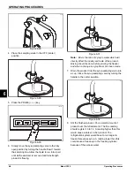
8. Insert the draw valve into the freezer door spout from
the front of the unit. The valve is properly installed
when the hole in the draw valve is visible in the slot of
the freezer door spout.
Figure 6-9
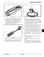
9. Snap the draw valve handle onto the door spout.
Align the hole in the draw valve with the slot in the
draw handle.
Figure 6-10
10189
11125
11126
11127
11128
Содержание C300 NP
Страница 14: ...3 4 SAFETY Model C300 Safety 3 Notes...
Страница 18: ...4 4 OPERATOR PARTS IDENTIFICATION Model C300 Operator Parts Identification 4 Notes...
Страница 26: ...5 8 USER INTERFACE Model C300 User Interface 5 Notes...
Страница 40: ...6 14 OPERATING PROCEDURES Model C300 Operating Procedures 6 Notes...
Страница 42: ...7 2 OPERATOR CHECKLIST Model C300 Operator Checklist 7 Notes...
Страница 46: ...9 2 Model C300 Parts Replacement Schedule PARTS REPLACEMENT SCHEDULE 9 Notes...
Страница 52: ...LIMITED WARRANTY ON PARTS 11 4 Model C300 Limited Warranty on Parts 11 Notes...