2
To the Installer
Models 702/741/772
050323
Check Out
Once the unit is installed, it is advisable to check the
following controls and mechanical operations of the
freezer and to make any necessary adjustments. If
applicable, repeat these checks for the second
freezing cylinder on double head units.
Controls
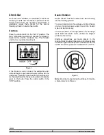
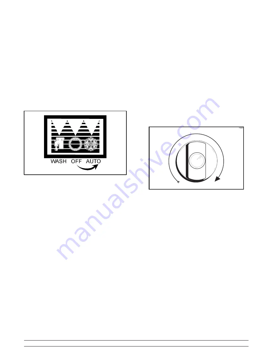
Place the control switch in the “AUTO” position. The
main refrigeration system will operate (compressor,
beater motor, and the condenser fan). The dial light
and the mix low indicator will be lit.
Figure 1
If the freezer is water cooled, the automatic water
valve will begin to open and cold water will flow into the
condenser. This will remove heat from the refrigerant.
As the water flows into the open trap drain, it should be
warm to the touch. Place the control switch in the
“OFF” position.
Beater Rotation
Beater rotation must be clockwise as viewed looking
into the freezing cylinder.
To correct rotation on a three-phase unit, interchange
any two incoming power supply lines at the freezer
main terminal block only.
To correct rotation on a single-phase unit, exchange
leads inside the beater motor. (Follow the diagram
printed on the motor.)
Electrical connections are made directly to the
terminal block provided in the main control box located
behind the upper left side panel for the Model 702, and
behind the service panel for the Model 741 and 772.
Figure 2
Note:
Electrical connections should be performed by
a trained service technican.
Содержание 702
Страница 1: ...0...
Страница 38: ...0RGHO...
Страница 39: ...0RGHO...
Страница 40: ...0RGHO...
Страница 41: ...0RGHO...
Страница 42: ...0RGHO...
Страница 43: ...0RGHO...


