


Front Axle
Page 34
RE-380-36 & RE-380-48
MR-380-05
FRONT WHEEL ALIGNMENT
Note: It is recommended to center the steering before aligning the front wheels. Refer to the Center the Steering
section for information.
1: Raise the front of the vehicle and support with jack
stands.
2: Position the steering wheel in the straight ahead
position and tie off the steering wheel so that it
cannot rotate.
3: Loosen the ball joint clamps on the drag link.
Note: Remember the position and orientation of the ball
joint clamps.
4: Adjust the drag link so that the center steering
linkage pivot arm is vertical.
5: Position the ball joint clamps in their original
location and orientation and tighten the ball joint
clamps.
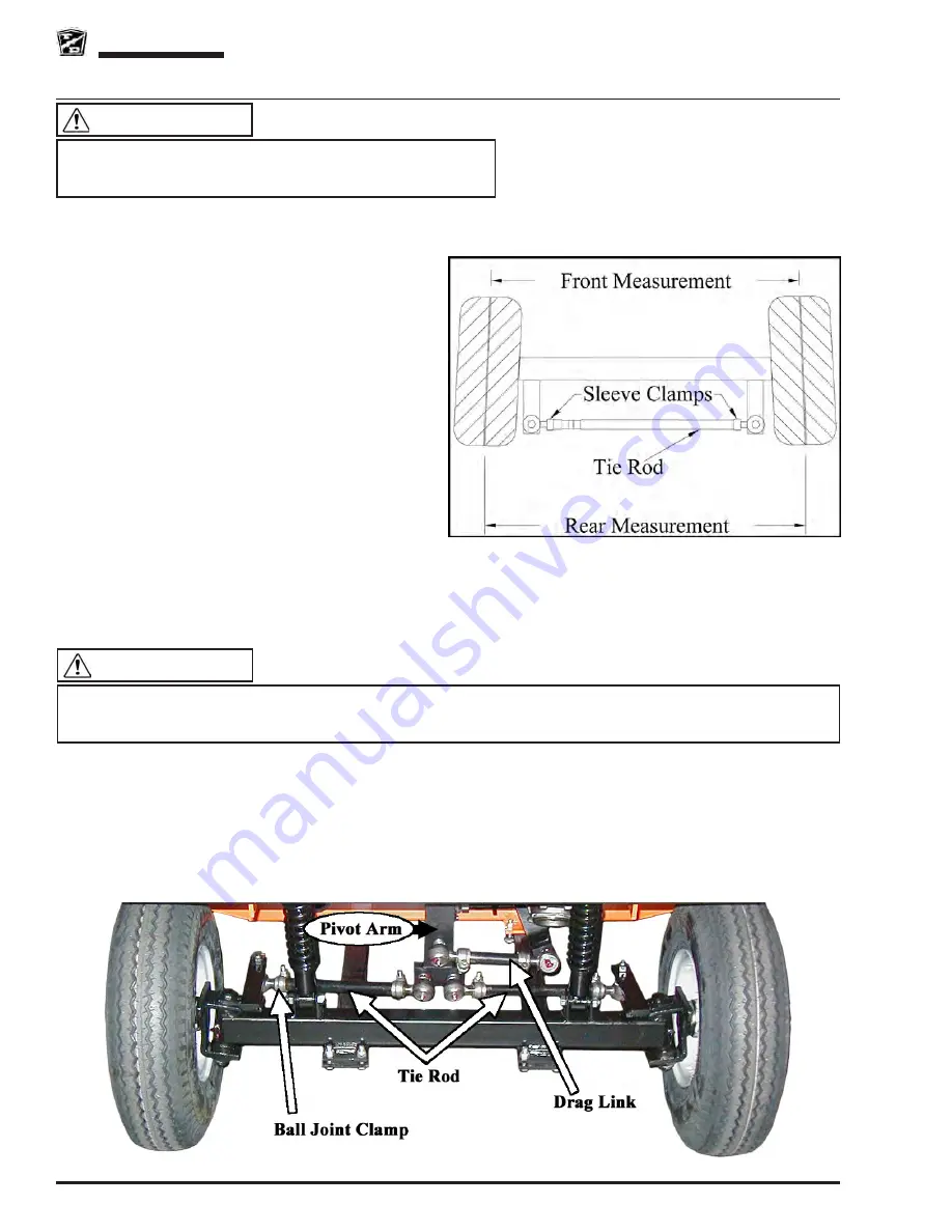
6: Using a piece of chalk, mark a line around the
center of both front tires.
7: Loosen the ball joint clamps on the left and right tie rods.
Note: Remember the position and orientation of the ball joint clamps.
8: Lower the front wheels to the ground and push the vehicle back and forth a few feet to settle the suspension.
9: Adjust the right side tie rod so that the right wheel is positioned pointing straight ahead.
10: Measure the distance between the lines at the front of the tires.
11: Measure the distance between the lines at the rear of the tires.
12: Adjust the left side tie rod so that the distance at the front and rear of the tires is the same.
13: Position the ball joint clamps in their original location and orientation and tighten the ball joint clamps.
14: Untie the steering wheel.
15: Reconnect the main positive and negative cables at the batteries.
16: Remove the blocks from behind the wheels.
17: Release the parking brake and test drive the vehicle.
This section is one section of a complete service manual. Before
starting any procedure, read all warnings and instructions that
are located in the Service Guidelines chapter.
WARNING
Rotate the steering wheel from a full left turn to a full right turn and make sure that the ball joint clamps do not
contact any other component. Clamps positioned so that they contact other components may result in steering
failure and loss of control of the vehicle causing severe bodily injury and/or property damage.
WARNING
Содержание RE-380-36
Страница 6: ......
Страница 12: ...Page 12 MR 380 05 Introduction RE 380 36 RE 380 48 Notes...
Страница 21: ...Table of Contents Special Tool List Special Tool List Controller Programming 22 Troubleshooting Guide 24...
Страница 27: ...Lubrication Page 27 MR 380 05 RE 380 36 RE 380 48 LUBRICATION DIAGRAM GT Transaxle SD Transaxle...
Страница 28: ...Lubrication Page 28 RE 380 36 RE 380 48 MR 380 05 Notes...
Страница 55: ...Transaxle SD Page 55 MR 380 05 RE 380 36 RE 380 48...
Страница 65: ...Steering Page 65 MR 380 05 RE 380 36 RE 380 48 Exploded View of Steering Gear...
Страница 89: ...Wire Diagram Page 89 RE 380 36 RE 380 48 RE 380 36 RE 380 48...
Страница 90: ...Wire Diagram Page 90 RE 380 36 RE 380 48 RE 380 36 RE 380 48 Notes...
Страница 102: ...Tires Wheels Page 102 RE 380 36 RE 380 48 MR 380 05 Notes...
Страница 112: ...Replacement Parts Page 112 MR 380 05 RE 380 36 RE 380 48 AXLE ASSEMBLY FRONT AXLE SHAFT ASSEMBLY REAR...
Страница 114: ...Replacement Parts Page 114 MR 380 05 RE 380 36 RE 380 48 GT TRANSAXLE ASSEMBLY REAR...
Страница 118: ...Replacement Parts Page 118 MR 380 05 RE 380 36 RE 380 48 BATTERY...
Страница 120: ...Replacement Parts Page 120 MR 380 05 RE 380 36 RE 380 48 BRAKES BRAKE LINES...
Страница 135: ...Replacement Parts Page 135 Not available at time of printing MR 380 05 RE 380 36 RE 380 48 FRAME AND BODY P4...
Страница 144: ...Replacement Parts Page 144 MR 380 05 RE 380 36 RE 380 48 STEERING LINKAGE...
Страница 149: ......