background image

71

VCB15_MD1_16D
17.5kV, 1250 A, PCD: 210 mm, with IP2X front cover, 
weight 88 kg


L

max

 = 677 mm

W

max

 = 682 mm

H

max

 = 633 mm

Содержание VCB15

Страница 1: ...WITHDRAWABLE VCB VACUUM CIRCUIT BREAKER 17 5kV 31 5kA 3150A 24kV 25kA 2500A PRODUCT GUIDE VERSION 6...

Страница 2: ......

Страница 3: ...nal Manual Generator Coding 22 4 Technical Parameters 23 5 Design and Operation 33 5 1 Design 34 5 1 1 Draw Out Unit 34 5 1 2 Indoor Switching Module 36 5 1 3 Control Module 38 5 2 Operation 39 5 2 1...

Страница 4: ......

Страница 5: ...1 Introduction...

Страница 6: ...rating principles The purpose of the document is to provide necessary product information for application engineers and technical personnel utilizing the equipment Other technical documents which cove...

Страница 7: ...please contact Tavrida Electric prior to usage of the withdrawable vacuum circuit breakers 1 4 Precautions Before selecting the circuit breaker please check whether the installation place Contact inte...

Страница 8: ...eriod of storage with the customer b The operating conditions ambient conditions transport and storage conditions have not been adhered to according to the application description or the Installation...

Страница 9: ...2 Presentation...

Страница 10: ...um circuit breakers with a rated current of 3150 A and a CM does not exceed 165 kg making it the most lightweight indoor circuit breaker on the market High reliability 30 000 CO operations at rated cu...

Страница 11: ...3 Product Coding...

Страница 12: ...or switching module with rated normal current up to 2500 A HD1 Three phase Heavy duty Indoor switching module with rated normal current up to 3150 A Table 3 CM and VCB Implementation Type Description...

Страница 13: ...CM NA Par9 Rated auxiliary supply voltage 24 60 V DC 60 110 220 V AC DC 220 Without CM NA Par10 Auxiliary plug Plastic plug 1 Metal plug 3 Par11 Optional interlock Without optional interlock 0 Electri...

Страница 14: ...The placement of the electrical data label is shown below a VCB15_LD8_16D labeling b VCB15_MD1_16D labeling d VCB25_Shell2_16D labeling c VCB15_HD1_16D labeling Figure 2 Electrical data label placeme...

Страница 15: ...ith rated normal current up to 2500 A Table 5 ISM Parameters Description Parameter Applicable ISM Parameter description Applicable options Code Par1 ISM15_LD_8 Phase centre distance 150 mm 150 210 mm...

Страница 16: ...hout protection 15HD1 000 ISM25_Shell_2 and Without protection 25Shell2 000 Par5 Factory configurable settings Relay 1 Switching module position functionality Relay 2 Ready functionality Relay 3 Malfu...

Страница 17: ...inals connections and main parameters Figure 8 CM labels arrangement 1 Serial number label 2 Label with applicable ISM designation 3 Warning label 4 Firmware version label 5 Information label with ter...

Страница 18: ...plug Plastic plug 1 Metal plug 3 CBkit_Plug_1 is used to provide a counterpart for the DOU auxiliary circuits connector in the switchgear panel 3 2 3 Auxiliary Plugs Kit Coding CBkit_Plug_1 Par1 Circu...

Страница 19: ...tor kit Kit type Table 8 Switchgear Kit Parameters Description Parameter Parameter description Applicable options Code Par1 Rated voltage 17 5 kV 17 5 24 kV 24 Par2 Rated normal current 1250 A 1250 20...

Страница 20: ...ity in case auxiliary voltage provided for solenoid installed on DOU plate is unavailable Figure 12 CBkit_Interlock_6 220U 3 2 5 Optional Circuit Breaker Interlock Kit Coding CBkit_Interlock_6 Par1 Ci...

Страница 21: ...mount_CM_1 Control module Kit type The CBmount_CM_1 is used to mount CM_16_1 on DIN rail Figure 13 CBmount_CM_1 3 2 6 Optional Kit for Control Module Installation on a DIN Rail Circuit breaker mountin...

Страница 22: ...ion Code N Description 1 Manual generator for use with CM_16_1 Par1_220 2_Par3_Par4_Par5 2 Manual generator for use with CM_16_1 Par1_60 2_Par3_Par4_Par5 3 2 7 Optional Manual Generator Coding Figure...

Страница 23: ...4 Technical Parameters...

Страница 24: ...ons 500 cycles 500 cycles 500 cycles Maximum number of CO cycles per hour 60 Operating cycles rated short circuit breaking current 50 50 50 Closing time 60 ms 5 Opening time 35 ms 5 Break time 45 ms 5...

Страница 25: ...0 3 100 mA Maximum current for 30 V DC ohmic load 10 A 10 Maximum current for 30 V DC inductive load t 20 ms 3 A Maximum current for 60 V DC ohmic load 0 9 A Maximum current for 60 V DC inductive loa...

Страница 26: ...ose and trip capacitors of CM_16_1 Par1_220 2_Par3_Par4_Par5 42 W AC 12 37 W DC Permanent power consumption standby of CM_16_1 Par1_60 2_Par3_Par4_Par5 5 W Permanent power consumption standby of CM_16...

Страница 27: ...with a 10 second interval should not exceed 10 The number of Close Trip operations should not exceed 60 per hour Sequence of 10s Close Trip operations can be repeated only after 260 s pause 7 Isolati...

Страница 28: ...breaking current 50 Closing time 60 ms 2 Opening time 35 ms 2 Break time 45 ms 2 Resistance of main circuit 35 Ohm for Ir 630 A 30 Ohm for Ir 1250 A 22 Ohm for Ir 2500 A Rated operating sequence at r...

Страница 29: ...ad 100 mA Minimum current for 12 V AC DC inductive load t 20 ms cosj 0 3 100 mA Maximum current for 30 V DC ohmic load 10 A 7 Maximum current for 30 V DC inductive load t 20 ms 3 A Maximum current for...

Страница 30: ...16_1 Par1_60 2_Par3_Par4_Par5 25 W Charging the close and trip capacitors of CM_16_1 Par1_220 2_Par3_Par4_Par5 42 W AC 9 37 W DC Permanent power consumption standby of CM_16_1 Par1_60 2_Par3_Par4_Par5...

Страница 31: ...rations can be repeated only after 260 s pause 4 Isolation resistance check is not applicable for Actuator Coil circuits of CM 5 Up to an installation altitude of 1000 m above sea level Above 1000m th...

Страница 32: ...ode Surge Immunity IEC 60255 26 IEC 61000 4 5 4 kV common mode 2 kV differential mode Conducted disturbance induced by Radio frequency fields IEC 60255 26 IEC 61000 4 6 150 kHz 80 MHz AM 1 kHz 80 10 V...

Страница 33: ...5 Design and Operation...

Страница 34: ...of the VCB can be provided as a design option The auxiliary circuit cable contains ISM and DOU auxiliary circuit switches and optional interlock wiring The auxiliary multi pin connector provides inter...

Страница 35: ...upper terminal 7 Main contact lower terminal The draw out plate auxiliary switches module is not shown in the Figure 19 Figure 18 VCB15_MD1_16D PCD 150 mm 1 Control wiring plug 2 Main contacts positi...

Страница 36: ...The draw out plate auxiliary switches module is not shown in the Figure 20 Figure 20 VCB25_Shell2_16D 1250 A PCD 210 mm Figure 21 ISM15_LD_8 5 1 2 Indoor Switching Module The Tavrida Electric vacuum c...

Страница 37: ...rs which combine small dimensions with an extraordinarily long mechanical and electrical lifespan The use of a specially designed axial magnetic field distribution provides even current density distri...

Страница 38: ...rcuit used to close or trip the ISM Therefore only one circuit connection between the ISM and the CM is required The CM can provide external circuits with information about the ISM main contacts state...

Страница 39: ...4 5 6 Figure 27 CM_16_1 8 5 2 Operation 5 2 1 VCB Racking In and Out of the Switchgear To change the VCB position from test to service and vice versa the DOU plate is equipped with a racking mechanis...

Страница 40: ...rge the CM capaci tors prior to applying the Close command to the ISM If manual generators CBunit_ManGen are used to charge the CM the manual generator handle shall be rotated until the Ready LED of t...

Страница 41: ...re 31 below The button moves the ISM synchronization plate When the synchronizing plate is moved a force exceeding the magnetic attraction forces of the ring magnet is applied to the ISM armature whic...

Страница 42: ......

Страница 43: ...6 Functionality...

Страница 44: ...ion Interlocks related to the draw out unit located inside the switchgear The draw out unit can only be moved when the earthing switch is open The earthing switch can only be closed when the draw out...

Страница 45: ...plate auxiliary switches 5 NO 5 NC switches indication provided by the ISM ISM main contacts position visual indication ISM main contacts position electrical indication ISM auxiliary switches 6 NO 6 N...

Страница 46: ...ply relay state Detailed explanations of the blink codes are provided in the Table 15 Table 15 CM Self Diagnostic Indication CM State Type of Indication Indication LED Power LED Ready LED Malfunction...

Страница 47: ...150 ms after the ISM main contacts closing If the Trip command was applied from the CM In this case the update is performed not later than in 70 ms after ISM main contacts opening Periodically every...

Страница 48: ......

Страница 49: ...7 Application Notes...

Страница 50: ...tion it is essential to verify the actual dimensions of the fixed contacts installed in the switchgear In the service position the connection of the VCB s flexible contacts with the fixed contacts of...

Страница 51: ...ion switch SQ1 10 39 ISM auxiliary switch XT3 9 11 DOU plate position switch SQ1 12 40 Earthing 12 ISM auxiliary switch XT3 1 41 ISM auxiliary switch XT3 11 13 42 DOU plate position switch SQ1 11 14 D...

Страница 52: ...ISM auxiliary switch XT2 8 63 DOU plate position switch SQ2 7 20 ISM auxiliary switch XT2 10 64 DOU plate position switch SQ2 8 21 ISM auxiliary switch XT2 12 65 22 ISM auxiliary switch XT3 8 66 Actua...

Страница 53: ...onnection 89 100 90 101 91 102 92 103 93 DOU plate position switch SQ1 9 104 94 DOU plate position switch SQ1 10 105 95 DOU plate position switch SQ1 11 106 96 DOU plate position switch SQ1 12 107 97...

Страница 54: ...ct the nearest Tavrida Electric sales representative for more information The CM is connected only to the ISM actuator coil circuits The position of the ISM main contacts is determined by detecting th...

Страница 55: ...hapter 4 If the manual generator CBunit_ManGen is used for charging its DC voltage outputs should be connected to power supply inputs of CM_16_1 Figure 41 CM_16 power supply connection Power supply in...

Страница 56: ......

Страница 57: ...Appendix 1 Type Tests...

Страница 58: ...on auxiliary and control equipment KEMA KEMA 1399 18 IEC 62271 200 6 102 2 Mechanical and electromechanical inter locks tests KEMA KEMA 2221 18 IEC 62271 100 6 6 Short time withstand current and peak...

Страница 59: ...5 Temperature rise tests on auxiliary and control equipment KEMA KEMA 1719 18 KEMA 1721 18 IEC 62271 200 6 102 2 Mechanical and electromechanical interlocks tests KEMA KEMA 2355 18 KEMA 2370 18 IEC 6...

Страница 60: ...im munity test KEMA KEMA TIC 1371 14 IEC 61000 4 10 1 MHz damped oscillatory magnetic field immunity test KEMA KEMA TIC 1371 14 IEC 60255 26 IEC 61000 4 11 AC voltage dips and interruptions immunity t...

Страница 61: ...Appendix 2 Withdrawable VCB Package Dimensions...

Страница 62: ...awable VCB PCD Package Dimensions not more than LxWxH mm VCB15_LD8_16D 150 780x780x937 210 780x780x937 VCB15_MD1_16D 150 780x780x937 210 780x780x937 VCB15_HD1_16D 210 780x780x937 275 1150x990x997 VCB2...

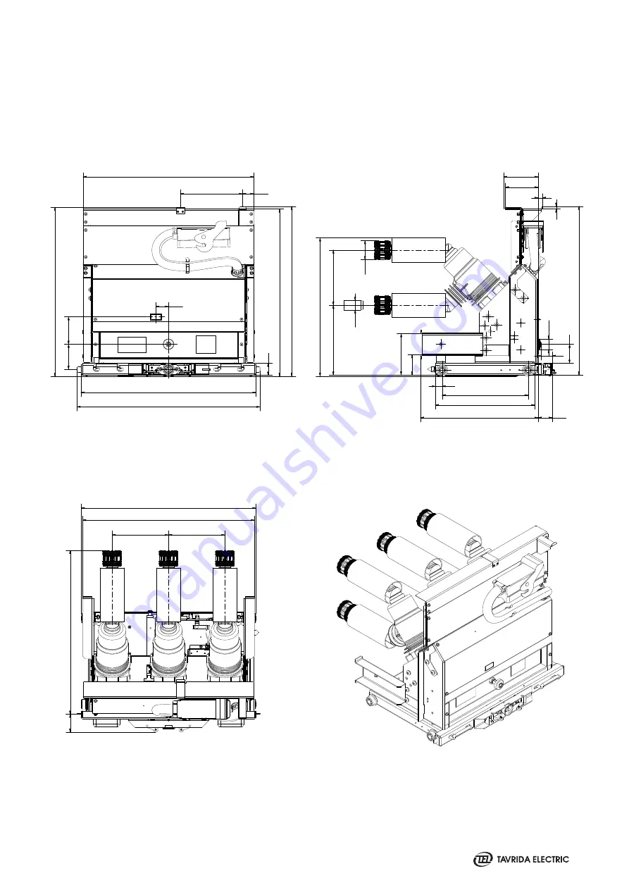
Страница 63: ...Appendix 3 Overall Drawings...

Страница 64: ...64 VCB15_LD8_16D 17 5kV 800 A PCD 150 mm weight 70 kg VCB15_LD8_16D Lmax 687 mm Wmax 535 mm Hmax 528 mm...

Страница 65: ...65 VCB15_LD8_16D 17 5kV 800 A PCD 210 mm weight 76 kg Lmax 677 mm Wmax 682 mm Hmax 528 mm...

Страница 66: ...66 VCB15_LD8_16D 17 5kV 800 A PCD 150 mm with IP2X front cover weight 74 kg Lmax 687 mm Wmax 535 mm Hmax 633 mm...

Страница 67: ...67 VCB15_LD8_16D 17 5kV 800 A PCD 210 mm with IP2X front cover weight 81 kg Lmax 677 mm Wmax 682 mm Hmax 633 mm...

Страница 68: ...68 VCB15_MD1_16D 17 5kV 1250 A PCD 150 mm weight 72 kg VCB15_MD1_16D Lmax 677 mm Wmax 535 mm Hmax 515 mm...

Страница 69: ...69 VCB15_MD1_16D 17 5kV 1250 A PCD 210 mm weight 74 kg Lmax 677 mm Wmax 682 mm Hmax 515 mm...

Страница 70: ...70 VCB15_MD1_16D 17 5kV 1250 A PCD 150 mm with IP2X front cover weight 76 kg Lmax 677 mm Wmax 535 mm Hmax 633 mm...

Страница 71: ...71 VCB15_MD1_16D 17 5kV 1250 A PCD 210 mm with IP2X front cover weight 88 kg Lmax 677 mm Wmax 682 mm Hmax 633 mm...

Страница 72: ...72 VCB15_HD1_16D VCB15_HD1_16D 17 5kV 2500 A PCD 210 mm weight 128 kg Lmax 656 5 mm Wmax 682 mm Hmax 704 mm...

Страница 73: ...73 VCB15_HD1_16D 17 5kV 2500 A PCD 275 mm weight 140 kg Lmax 656 5 mm Wmax 882 mm Hmax 704 mm...

Страница 74: ...74 VCB15_HD1_16D 17 5kV 3150 A PCD 275 mm weight 158 kg Lmax 656 5 mm Wmax 882 mm Hmax 704 mm...

Страница 75: ...75 VCB15_HD1_16D 17 5kV 2500 A PCD 210 mm with IP2X front cover weight 133 kg Lmax 656 5 mm Wmax 682 mm Hmax 704 mm...

Страница 76: ...76 VCB15_HD1_16D 17 5kV 2500 A PCD 275 mm with IP2X front cover weight 147 kg Lmax 656 5 mm Wmax 882 mm Hmax 704 mm...

Страница 77: ...77 VCB15_HD1_16D 17 5kV 3150 A PCD 275 mm with IP2X front cover weight 165 kg Lmax 656 5 mm Wmax 882 mm Hmax 742 mm...

Страница 78: ...78 VCB25_Shell2_16D VCB25_Shell2_16D 24kV 630 A PCD 210 mm 370 mm depth of movable part of cassette weight 101 kg Lmax 813 5 mm Wmax 682 mm Hmax 695 mm...

Страница 79: ...79 VCB25_Shell2_16D 24kV 1250 A PCD 210 mm 370 mm depth of movable part of cassette weight 112 kg Lmax 813 5 mm Wmax 682 mm Hmax 694 mm...

Страница 80: ...80 VCB25_Shell2_16D 24kV 630 A PCD 275 mm 370 mm depth of movable part of cassette weight 115 kg Lmax 813 5 mm Wmax 882 mm Hmax 695 mm...

Страница 81: ...81 VCB25_Shell2_16D 24kV 1250 A PCD 275 mm 370 mm depth of movable part of cassette weight 126 kg Lmax 813 5 mm Wmax 882 mm Hmax 694 mm...

Страница 82: ...82 VCB25_Shell2_16D 24kV 2500 A PCD 275 mm 370 mm depth of movable part of cassette weight 180 kg Lmax 803 5 mm Wmax 882 mm Hmax 719 mm...

Страница 83: ...83 VCB25_Shell2_16D 24kV 630 A PCD 210 mm 420 mm depth of movable part of cassette weight 102 kg Lmax 813 5 mm Wmax 682 mm Hmax 695 mm...

Страница 84: ...84 VCB25_Shell2_16D 24kV 1250 A PCD 210 mm 420 mm depth of movable part of cassette weight 113 kg Lmax 813 5 mm Wmax 682 mm Hmax 694 mm...

Страница 85: ...85 VCB25_Shell2_16D 24kV 630 A PCD 275 mm 420 mm depth of movable part of cassette weight 117 kg Lmax 813 5 mm Wmax 882 mm Hmax 695 mm...

Страница 86: ...86 VCB25_Shell2_16D 24kV 1250 A PCD 275 mm 420 mm depth of movable part of cassette weight 128 kg Lmax 813 5 mm Wmax 882 mm Hmax 694 mm...

Страница 87: ...87 VCB25_Shell2_16D 24kV 2500 A PCD 275 mm 420 mm depth of movable part of cassette weight 163 kg Lmax 803 5 mm Wmax 882 mm Hmax 719 mm...

Страница 88: ...88 VCB25_Shell2_16D 24kV 630 A PCD 210 mm 370 mm depth of movable part of cassette with IP2X front cover weight 109 kg Lmax 813 5 mm Wmax 682 mm Hmax 792 mm...

Страница 89: ...89 VCB25_Shell2_16D 24kV 1250 A PCD 210 mm 370 mm depth of movable part of cassette with IP2X front cover weight 120 kg Lmax 813 5 mm Wmax 682 mm Hmax 792 mm...

Страница 90: ...90 VCB25_Shell2_16D 24kV 630 A PCD 275 mm 370 mm depth of movable part of cassette with IP2X front cover weight 124 kg Lmax 813 5 mm Wmax 882 mm Hmax 792 mm...

Страница 91: ...91 VCB25_Shell2_16D 24kV 1250 A PCD 275 mm 370 mm depth of movable part of cassette with IP2X front cover weight 135 kg Lmax 813 5 mm Wmax 882 mm Hmax 792 mm...

Страница 92: ...92 VCB25_Shell2_16D 24kV 2500 A PCD 275 mm 370 mm depth of movable part of cassette with IP2X front cover weight 190 kg Lmax 803 5 mm Wmax 882 mm Hmax 836 mm...

Страница 93: ...93 VCB25_Shell2_16D 24kV 630 A PCD 210 mm 420 mm depth of movable part of cassette with IP2X front cover weight 110 kg Lmax 813 5 mm Wmax 682 mm Hmax 792 mm...

Страница 94: ...94 VCB25_Shell2_16D 24kV 1250 A PCD 210 mm 420 mm depth of movable part of cassette with IP2X front cover weight 121 kg Lmax 813 5 mm Wmax 682 mm Hmax 792 mm...

Страница 95: ...95 VCB25_Shell2_16D 24kV 630 A PCD 275 mm 420 mm depth of movable part of cassette with IP2X front cover weight 126 kg Lmax 813 5 mm Wmax 882 mm Hmax 792 mm...

Страница 96: ...96 VCB25_Shell2_16D 24kV 1250 A PCD 275 mm 420 mm depth of movable part of cassette with IP2X front cover weight 137 kg Lmax 813 5 mm Wmax 882 mm Hmax 792 mm...

Страница 97: ...97 VCB25_Shell2_16D 24kV 2500 A PCD 275 mm 420 mm depth of movable part of cassette with IP2X front cover weight 173 kg Lmax 803 5 mm Wmax 882 mm Hmax 836 mm...

Страница 98: ...98 CM_16_1 Par1_Par2_Par3_Par4_Par5 Weight 1 kg Dimensions of Control Module 165 190 45 177 16 2 2 165 120 25 5 159 5 4 5 1 11 Lmax 165 mm Wmax 190 mm Hmax 45 mm...

Страница 99: ...mensions of the Accessories Control Wiring Plug Counterparts Dimensions of Manual Generator CBunit_ManGen_1 CBunit_ ManGen_2 Control wiring plastic plug counterpart Control wiring plastic plug counter...

Страница 100: ...100 Control wiring metal plug counterpart 17 5 kV 1250 A fixed contact Switchgear Fixed Contact Counterparts...

Страница 101: ...101 3 n 3B 3B 24 kV 1250 A fixed contact 2000 A fixed contact...

Страница 102: ...102 3150 A fixed contact...

Страница 103: ...Appendix 4 Secondary Schemes...

Страница 104: ...104 VCB15_LD8_16D with Plastic Plug...

Страница 105: ...105 VCB15_LD8_16D with Metal Plug...

Страница 106: ...osition ISM Indoor switching module IGBT Transistor bridge coils control S1 S12 Auxiliary switch of ISM S13 S14 Auxiliary switch for ISM electrical interlock S13 S14 are at inactivated position S15 Au...

Страница 107: ...ssed at test position ISM Indoor switching module IGBT Transistor bridge coils control S1 S12 Auxiliary switch of ISM S13 S14 Auxiliary switch for ISM electrical interlock S13 S14 are at inactivated p...

Страница 108: ...osition ISM Indoor switching module IGBT Transistor bridge coils control S1 S12 Auxiliary switch of ISM S13 S14 Auxiliary switch for ISM electrical interlock S13 S14 are at inactivated position S15 Au...

Страница 109: ...d at test position ISM Indoor switching module IGBT Transistor bridge coils control S1 S12 Auxiliary switch of ISM S13 S14 Auxiliary switch for ISM electrical interlock S13 S14 are at inactivated posi...

Страница 110: ...PNFS TQFDJGJDBUJPO 42 42 BSF TIPX JO GSFF QPTJUJPO 42 JT QSFTTFE BU TFSWJDF QPTJUJPO 42 JT QSFTTFE BU UFTU QPTJUJPO 4 OEPPS TXJUDIJOH NPEVMF 5 5SBOTJTUPS CSJEHF DPJMT DPOUSPM 4 4 VYJMJBSZ TXJUDI PG 4...

Страница 111: ...essed at test position ISM Indoor switching module IGBT Transistor bridge coils control S1 S12 Auxiliary switch of ISM S13 S14 Auxiliary switch for ISM electrical interlock S13 S14 are at inactivated...

Страница 112: ...2 21 02 2019 Mistypes correction Document elaboration may 3 09 10 2019 Change of VCB ISM and CM classification Product range change may 4 29 10 2019 Adding of the CBmount_CM_1 Product range change ma...

Страница 113: ......

Страница 114: ......

Страница 115: ......

Страница 116: ...GDOU EN _6 Version Rev 6 Date 12 08 2022 www tavrida com Brazil Tavrida Electric do Brazil Av Ireno da Silva Ven ncio 199 GP04A Protestantes Votorantim SP Brazil Phone 55 15 3243 2555 Fax 55 15 3243 4...

Отзывы: