


45
6.2 Optional interlocks
6.3 Indication
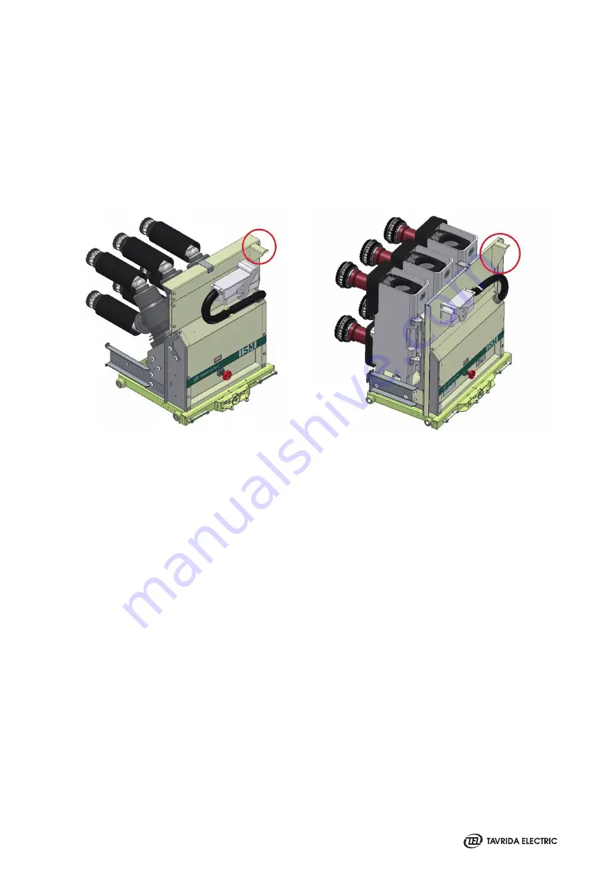
Optionally the VCB can be equipped with the following interlocks (in any combination):
• The Interlock preventing VCB auxiliary circuits plug connection to the switchgear if the VCB is not in the test
position. The interlock is available when the VCB has plastic auxiliary circuits plug. In case the VCB has IP2X front
cover it is already equipped with this interlock;
• The interlock preventing the draw-out unit racking in/out in case locking solenoid is not energized.
Figure 35
Auxiliary circuits plug interlock
The VCB has the following indication functionality:
• indication provided by the DOU plate:
- DOU plate position – DOU plate auxiliary switches (5 NO+5 NC switches).
• indication provided by the ISM:
- ISM main contacts position (visual indication);
- ISM main contacts position (electrical indication) – ISM auxiliary switches (6 NO+6 NC switches).
• indication provided by the CM:
- ISM main contacts position (electrical indication) – one
1)
built-in CM relay (1 NO + 1 NC with common point);
- CM “Power“ indication – LED indicator;
- CM “Ready“ state indication – LED indicator and one built in CM relay (1 NO + 1 NC with common point);
- CM “Malfunction“ state indication – LED indicator and one built-in CM relay (1 NO + 1 NC with common
point).
Technical data for the ISM and the DOU plate auxiliary switches load and built-in and CM relays is provided in
Chapter 4.
1) The number of CM relays indicating ISM main circuits position can be increased for certain applications, please contact your nearest sales
representative for details.
Содержание VCB15
Страница 1: ...WITHDRAWABLE VCB VACUUM CIRCUIT BREAKER 17 5kV 31 5kA 3150A 24kV 25kA 2500A PRODUCT GUIDE VERSION 6...
Страница 2: ......
Страница 4: ......
Страница 5: ...1 Introduction...
Страница 9: ...2 Presentation...
Страница 11: ...3 Product Coding...
Страница 23: ...4 Technical Parameters...
Страница 33: ...5 Design and Operation...
Страница 42: ......
Страница 43: ...6 Functionality...
Страница 48: ......
Страница 49: ...7 Application Notes...
Страница 56: ......
Страница 57: ...Appendix 1 Type Tests...
Страница 61: ...Appendix 2 Withdrawable VCB Package Dimensions...
Страница 63: ...Appendix 3 Overall Drawings...
Страница 64: ...64 VCB15_LD8_16D 17 5kV 800 A PCD 150 mm weight 70 kg VCB15_LD8_16D Lmax 687 mm Wmax 535 mm Hmax 528 mm...
Страница 65: ...65 VCB15_LD8_16D 17 5kV 800 A PCD 210 mm weight 76 kg Lmax 677 mm Wmax 682 mm Hmax 528 mm...
Страница 66: ...66 VCB15_LD8_16D 17 5kV 800 A PCD 150 mm with IP2X front cover weight 74 kg Lmax 687 mm Wmax 535 mm Hmax 633 mm...
Страница 67: ...67 VCB15_LD8_16D 17 5kV 800 A PCD 210 mm with IP2X front cover weight 81 kg Lmax 677 mm Wmax 682 mm Hmax 633 mm...
Страница 68: ...68 VCB15_MD1_16D 17 5kV 1250 A PCD 150 mm weight 72 kg VCB15_MD1_16D Lmax 677 mm Wmax 535 mm Hmax 515 mm...
Страница 69: ...69 VCB15_MD1_16D 17 5kV 1250 A PCD 210 mm weight 74 kg Lmax 677 mm Wmax 682 mm Hmax 515 mm...
Страница 72: ...72 VCB15_HD1_16D VCB15_HD1_16D 17 5kV 2500 A PCD 210 mm weight 128 kg Lmax 656 5 mm Wmax 682 mm Hmax 704 mm...
Страница 73: ...73 VCB15_HD1_16D 17 5kV 2500 A PCD 275 mm weight 140 kg Lmax 656 5 mm Wmax 882 mm Hmax 704 mm...
Страница 74: ...74 VCB15_HD1_16D 17 5kV 3150 A PCD 275 mm weight 158 kg Lmax 656 5 mm Wmax 882 mm Hmax 704 mm...
Страница 100: ...100 Control wiring metal plug counterpart 17 5 kV 1250 A fixed contact Switchgear Fixed Contact Counterparts...
Страница 101: ...101 3 n 3B 3B 24 kV 1250 A fixed contact 2000 A fixed contact...
Страница 102: ...102 3150 A fixed contact...
Страница 103: ...Appendix 4 Secondary Schemes...
Страница 104: ...104 VCB15_LD8_16D with Plastic Plug...
Страница 105: ...105 VCB15_LD8_16D with Metal Plug...
Страница 113: ......
Страница 114: ......
Страница 115: ......


