


40
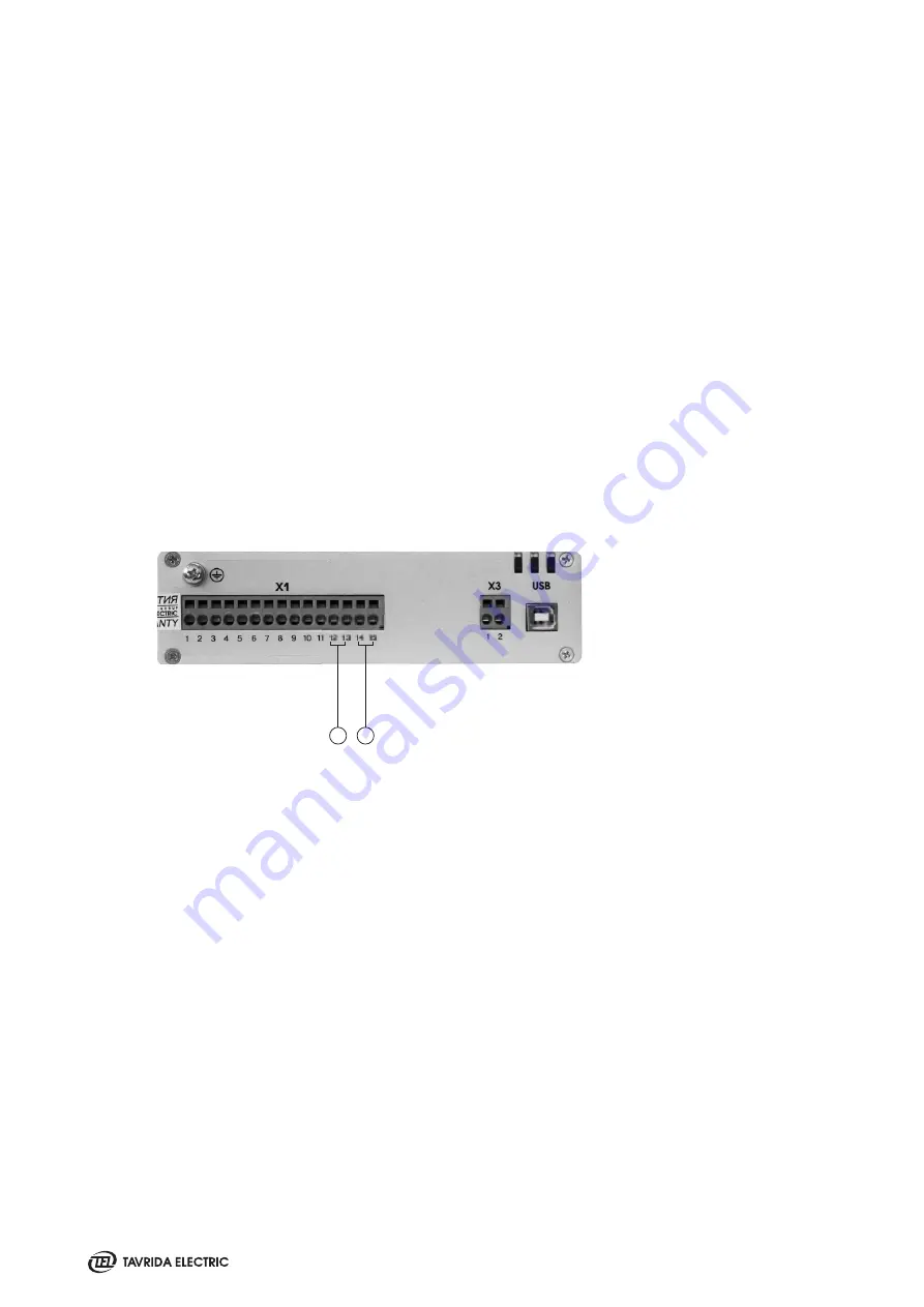
1. Close command input
2. Trip command input
1
2
Figure 30
CM_16_1 close and trip inputs
5.2.2 ISM Closing
To close the ISM main contacts, the CM close command should be applied. It is a “dry contact“ input; no external
voltage is required.
The close command will be accepted in the following cases:
• The CM state is “Ready” (Ready LED flashes green).
• No Trip command is applied.
• Mechanical and electrical interlock is unlocked.
If the “Close” command is applied and held before the CM is in a “Ready“ state, the Close command will not be
accepted.
If auxiliary power is unavailable, the manual generator CBunit_ManGen should be used to charge the CM capaci-
tors prior to applying the “Close” command to the ISM.
If manual generators CBunit_ManGen are used to charge the CM, the manual generator handle shall be rotated
until the Ready LED of the CM flashes green (approximately 30 seconds). Then the ISM close command can be
applied to the CM.
5.2.3 ISM Opening
To open the ISM main circuits, a trip command should be applied to the CM trip command input. It is a “dry
contact“ input, so no external voltage should be applied.
The trip command will be accepted if CM state is “Ready” (Ready LED flashes green), even up to 60 seconds after
a loss of auxiliary power supply.
If the trip command is applied and kept before the CM is in a “Ready“ state, the trip command will be accepted
after the CM is in a “Ready“ state. Holding the “Trip” command will block the “Close” command execution.
Содержание VCB15
Страница 1: ...WITHDRAWABLE VCB VACUUM CIRCUIT BREAKER 17 5kV 31 5kA 3150A 24kV 25kA 2500A PRODUCT GUIDE VERSION 6...
Страница 2: ......
Страница 4: ......
Страница 5: ...1 Introduction...
Страница 9: ...2 Presentation...
Страница 11: ...3 Product Coding...
Страница 23: ...4 Technical Parameters...
Страница 33: ...5 Design and Operation...
Страница 42: ......
Страница 43: ...6 Functionality...
Страница 48: ......
Страница 49: ...7 Application Notes...
Страница 56: ......
Страница 57: ...Appendix 1 Type Tests...
Страница 61: ...Appendix 2 Withdrawable VCB Package Dimensions...
Страница 63: ...Appendix 3 Overall Drawings...
Страница 64: ...64 VCB15_LD8_16D 17 5kV 800 A PCD 150 mm weight 70 kg VCB15_LD8_16D Lmax 687 mm Wmax 535 mm Hmax 528 mm...
Страница 65: ...65 VCB15_LD8_16D 17 5kV 800 A PCD 210 mm weight 76 kg Lmax 677 mm Wmax 682 mm Hmax 528 mm...
Страница 66: ...66 VCB15_LD8_16D 17 5kV 800 A PCD 150 mm with IP2X front cover weight 74 kg Lmax 687 mm Wmax 535 mm Hmax 633 mm...
Страница 67: ...67 VCB15_LD8_16D 17 5kV 800 A PCD 210 mm with IP2X front cover weight 81 kg Lmax 677 mm Wmax 682 mm Hmax 633 mm...
Страница 68: ...68 VCB15_MD1_16D 17 5kV 1250 A PCD 150 mm weight 72 kg VCB15_MD1_16D Lmax 677 mm Wmax 535 mm Hmax 515 mm...
Страница 69: ...69 VCB15_MD1_16D 17 5kV 1250 A PCD 210 mm weight 74 kg Lmax 677 mm Wmax 682 mm Hmax 515 mm...
Страница 72: ...72 VCB15_HD1_16D VCB15_HD1_16D 17 5kV 2500 A PCD 210 mm weight 128 kg Lmax 656 5 mm Wmax 682 mm Hmax 704 mm...
Страница 73: ...73 VCB15_HD1_16D 17 5kV 2500 A PCD 275 mm weight 140 kg Lmax 656 5 mm Wmax 882 mm Hmax 704 mm...
Страница 74: ...74 VCB15_HD1_16D 17 5kV 3150 A PCD 275 mm weight 158 kg Lmax 656 5 mm Wmax 882 mm Hmax 704 mm...
Страница 100: ...100 Control wiring metal plug counterpart 17 5 kV 1250 A fixed contact Switchgear Fixed Contact Counterparts...
Страница 101: ...101 3 n 3B 3B 24 kV 1250 A fixed contact 2000 A fixed contact...
Страница 102: ...102 3150 A fixed contact...
Страница 103: ...Appendix 4 Secondary Schemes...
Страница 104: ...104 VCB15_LD8_16D with Plastic Plug...
Страница 105: ...105 VCB15_LD8_16D with Metal Plug...
Страница 113: ......
Страница 114: ......
Страница 115: ......