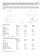
ELECTRICAL CONNECTIONS (SPEED 2 - 5 - 8)
CONEXIONES ELÉCTRICAS (SPEED 2 - 5 - 8)
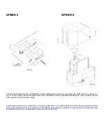
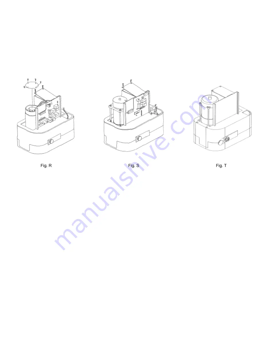
To connect remove the casing from the geared motor, the electrical components stand and only for SPEED 2 the cover of
transformer, Fig. R. Carry all cables across the holes obtained from the foundation' s base counter plate and across the inferior
base of geared motor and
dispose them for the connection:
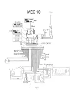
1. To the stabilization card positioned under the cover of the transformer for the SPEED 2;
2. To the principal card placed in the electrical components stand for SPEED 5 - 8.
Use cables with a minimum cross section of 1.5 mm2 for the power circuits and 0.5 mm2 for the control circuits.
Para realizar las conexiones eléctricas, sacar el cárter del motorreductor, el soporte componentes eléctricos y, sólo para
el SPEED 2, la tapa del transformador, fig. R. Introducir los cables de alimentación a través de los agujeros existentes en
la contraplaca de cimentación (cuando ésta se utilice); pasarlos a través del cuerpo inferior del motorreductor y
prepararlos para la conexión:
1. Con la ficha estabilizadora, colocada bajo la tapa del transformador para el SPEED 2.
2. Con la ficha de mando, situada en el soporte componentes eléctricos para el SPEED 5 y para el SPEED 8.
Emplear cables de una sección mínima de 1,5 mm2 para los circuitos de potencia y de 0.5 mm2 para los circuitos de
mando.
Содержание speed 2
Страница 10: ...Fig U...
Страница 11: ...Fig V...


