


18
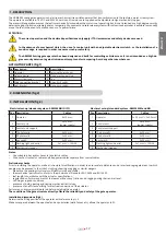
ENGLISH
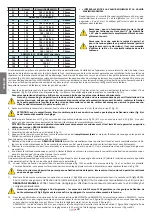
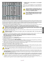
X°
A (mm)
B (mm) [ARM2000IFC]
C (mm)
÷ = RANGE BETWEEN PERMITTED MINIMUM AND MAXIMUM VAL-
UES
When distance “C” is greater/smaller than 20 mm, increase/decrease
distance “B” by the difference (e.g.: if C = 25mm, increase “B” by 5mm),
making sure that it does not exceed the limits shown in the chart.
Note: to work correctly, the angle formed by the ac-
tuator and the gate (Y°, pic. 4) must be ≥ 2° both with
the gate completely closed and completely open.
Note: for a quick opening and optimum closed-holding
position (gates with an electrical lock), use the maxi-
mum distance “B” shown in the chart.
90
145
150 ÷ 190 [180]
20 mm
90
150
150 ÷ 185 [175]
20 mm
ARM2000IFC Ideal size :
90
155
155
20 mm
90
155
150 ÷ 180 [165]
20 mm
90
160
150 ÷ 170 [160]
20 mm
90
165
150 ÷ 165 [150]
20 mm
90
170
150 ÷ 155 [--]
20 mm
90
175
150 [--]
20 mm
95
150
150 ÷ 185 [165]
20 mm
95
155
150 ÷ 180 [160]
20 mm
95
160
150 ÷ 170 [155]
20 mm
95
165
150 ÷ 165 [--]
20 mm
95
170
150 ÷ 155 [--]
20 mm
ARM2000IS/IF - ARM2000BI Ideal size :
100
165
155
20 mm
100
165
150 ÷ 155 [--]
20 mm
100
170
150 [--]
20 mm
105
180
150
20 mm
I
f the pillar dimensions or the hinge position do not allow the installation of the operator, a niche on the pillar, as shown in pic. 5, should be
created in order to maintain the A distance as determined. The niche should be dimensioned in such a way to enable easy installation, actuator
rotation and operation of the release device. The mounting brackets are designed to enable small adjustments in both directions (pic. 5A), it
is possible to use the two multipoint brackets overlapped (pic. 5B: in this case the only holes to be used are the 3 highlighted, according to the
direction of the leaf movement). In any case, always refer to the measurements shown in the table.
Please keep to the values given in the table and oil the gate’s hinges.
1_ Fix the rear bracket in the position determined before. In the event of iron pillar carefully weld directly the bracket or use 4 suitable screws
(pic. 6). In the event of brick pillar (pic. 7), use 4 suitable bolts (after you have assembled the bracket, pic. 7A).
During the fastening operations, check if the bracket is perfectly horizontal by means of a level.
WARNING - In case of large gate leaves and/or closed design leaves, other than the installation of an electro lock it is sug-
gested to strengthen the fastening of the back bracket (weld the steel parts instead of using screws to assemble the bracket,
use steel anchors instead of the dowels, weld the bracket onto the pillar, etc.).
2_ After removing the terminal board cover, anchor the actuator to the rear bracket using the screw and nut supplied (see 1, pic. 8);
ATTENTION: carefully verify that, when gate is closed, the actuator’s rear do not touch the bracket (see pic. 8). If so adjust the
setting accordingly.
3_ Make sure that the lead screw carrier block (1, pic. 9A) is in the position as shown in pic.9A (at a distance of approx. 10 mm from the cap). If
this is not the case, in order to adjust the position of the lead screw carrier block, the gate operator should be momentarily powered.
ATTENTION: The operator can be moved by hand only if it is installed on the gate and in released position (see MANUAL RELEASE).
4_ check the distance “C” (pic. 4);
5_ assemble the leaf bracket as shown in pic.10;
6_ rest the bracket that has just been fixed, onto the leaf of the completely closed gate and mark height of welding or the fixing points (make
sure it is level, see pic. 11).
Before going on to the next phase please carry out the following test:
7_ release the actuator (see
MANUAL RELEASE) and manually check if the gate can completely open without hindrances and stop at the me-
chanical stoppers (or floor-mounted mechanical stoppers) as well as if the leaf moves regularly without any friction.
8_ carry out the necessary corrective measures and repeat from point 7. Manually open the gate to the maximum required angle;
9_ using the same method as in point 3, position the lead screw carrier block towards the motor until the leaf bracket overleaps the position
previously marked on the leaf. If it does, the installation nas been prperly done.
This procedure can be used to establish where the leaf bracket should be welded for each opening angle (X°), provided it is possible (parameters
A and B as well as the stroke must allow it).
10_ weld the leaf bracket in the position indicated (pic.12A), according to pic. 13 and ensuring the planarity of the assembly. Alternatively, you
can use the multipoint bracket, to be assembled as shown in pic. 12B.
Note: if the gate structure does not allow a fix bracket fastening it is necessary to create a sturdy supporting base in the gate
structure.
11_ Move the open (opzional) mechanical stopper (1, pic. 9B) to enable opening of the leaf to the required angle. To access the locking screws
of the mechanical stopper (2, pic.9B), the operator needs to be moved manually (see MANUAL RELEASE). Check the precision of the setting
by performing a manual cycle with the actuator released, making corrections if necessary.
Note: next settings to increase the stroke of the operator WILL NOT be possible, as the fastening dowels of the mechanical
stopper (2 pic. 9B) incise the endless screw, compromising the correct sliding of the fork.
12_ When a gate operator with limit switch is used (ARM2000IF or ARM2000IFC), proceed as follows:
ARM2000IF: nominal stroke is 350 mm; to adjust stroke, loosen the locking nuts (1, pic. 2A) and set the limit switch to the required position.
Max. adjustment is 50 mm. Once the adjustment is completed, tighten the locking nuts again (1, pic. 2A).
ARM2000IFC: nominal stroke is 340 mm; to adjust stroke, loosen the locking nuts (1, pict. 2B) and set the limit switch to the required posi-
tion. Max. adjustment is 50 mm. One the adjustment is completed, tighten the locking nuts again (1 pict. 2B).
Note: for complete safety, both OPEN and CLOSE floor-mounted mechanical stoppers must be installed (8, pic.3).