
MMR-8
Tascam MMR-8 Owner’s Manual • Chapter 3 • MMR-8 Operation
39
Liquid Crystal Display (LCD)
The LCD or “display” consists of two lines of twenty characters that show various operator messages
(time code, user prompts, error messages and information, track data, and setup menu information)
depending upon the active panel/display state. Both lines of the LCD can also show various system
messages according to the operating state. Typically the top line will indicate the current time code
position in the Normal state, the Setup menu number and item in the Setup state, and the Track
information or action instruction in the Track states. In the Verify or Error states, additional text may be
displayed in the bottom line of the display, depending upon the message or error generated.
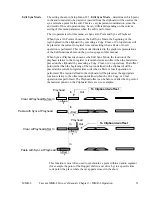
In cases where the message exceeds the width of the LCD window, the left/right arrow keys can be used
to horizontally scroll the message. The window follows the arrow key movement (right-arrow moves the
window to the right and left-arrow moves the window to the left), thus scrolling the text across the LCD
in the opposite direction. The appearance of the LCD in each of the MMR panel/display states is
described in detail here.
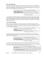
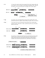
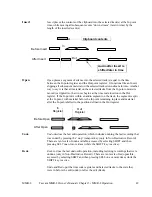
Normal State Display
In the Normal state, the top line shows the current transport status and the current position of the “play
head” in either SMPTE/EBU time code or in feet & frames. The bottom line of the display shows the time
code entry register or most recently accessed time code register. The display format selected is kept as
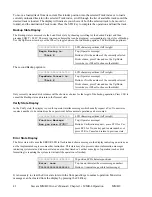
part of the user settings file. The following illustrates the Normal state display of just the top line for time
code and for feet & frames:
01234567890123456789
the 20 LCD character positions
cd HH:MM:SS:FF.xx
(Top Line Display for time code)
cd TTTTT FF.xx
(Top Line Display for feet & frames)
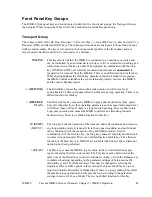
“cd” is a one or two character display code for the current state of the MMR-8 transport:
o
Indicates the transport is stopped
> Indicates the system is in play mode but unlocked
>L Indicates the system is locked and in play
< Indicates the system is in reverse play
>> Indicates the system is in fast forward
<< Indicates the system is in rewind
In Shuttle or Jog the display will show <<, <, > or >> according to the movement of the Wheel. The Time Code
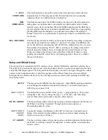
and Feet & Frames characters shown in the Normal state display are:
HH
- the hour display (01 - 23)
MM
- the minutes display (00 - 59)
SS
- the seconds display (00 - 59)
FF
-the frame number (00-29)
xx
- the subframe number (00 - 99)*
TTTTT
is the film footage count (00000 - 99999)
* Subframes is an optional display characteristic.
Содержание MMR-8
Страница 5: ......
Страница 6: ......
Страница 7: ......
Страница 8: ......
Страница 9: ......
Страница 38: ...32 Tascam MMR 8 User s Guide Chapter 3 MMR 8 Operation MMR 8...
Страница 42: ...36...
Страница 94: ...Tascam MMR 8 Owner s Manual Appendix A Control Panel Summary 88...
Страница 110: ...Tascam MMR 8 Owner s Manual Appendix E Glossary 104...
Страница 123: ...Tascam MMR 8 Owner s Manual Index 117...