


Tascam MMR-8 Owner’s Manual • Appendix D • Cable Information
99
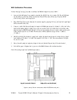
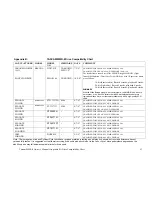
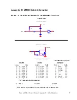
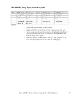
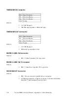
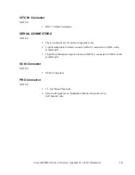
TRANSPORT (Sony 9-pin) Connector pinout
PIN #
MSTR Signal
SLAVE Signal
Pin #
MSTR Signal
SLAVE Signal
1
Frame ground
Frame ground
6
Frame ground
Frame ground
2
Receive -
Transmit -
7
R
Tr
3
Tr
R
8
Transmit -
Receive -
4
Frame ground
Frame ground
9
Frame ground
Frame ground
5
Spare Fr Ck
Spare Fr Ck
NOTES:
1. 9-pin D-subminiature female connector (DB-9).
2. Signals are RS422 Compatible Frame Clock spare should not be used.
3. The two connectors allow parallel connection of the Lynx Bus. Each pin is
paralleled internally between the two connectors. The signal description
indicates master / slave signals.
4. Signal Descriptions are MMR Output / Transport (Input). Signals are of
Protocol-2 (P-2) standard, which is also known as Sony 9-pin
Содержание MMR-8
Страница 5: ......
Страница 6: ......
Страница 7: ......
Страница 8: ......
Страница 9: ......
Страница 38: ...32 Tascam MMR 8 User s Guide Chapter 3 MMR 8 Operation MMR 8...
Страница 42: ...36...
Страница 94: ...Tascam MMR 8 Owner s Manual Appendix A Control Panel Summary 88...
Страница 110: ...Tascam MMR 8 Owner s Manual Appendix E Glossary 104...
Страница 123: ...Tascam MMR 8 Owner s Manual Index 117...