TASCAM M-3500 MIXING CONSOLE
4
CHANNEL FADER SECTION
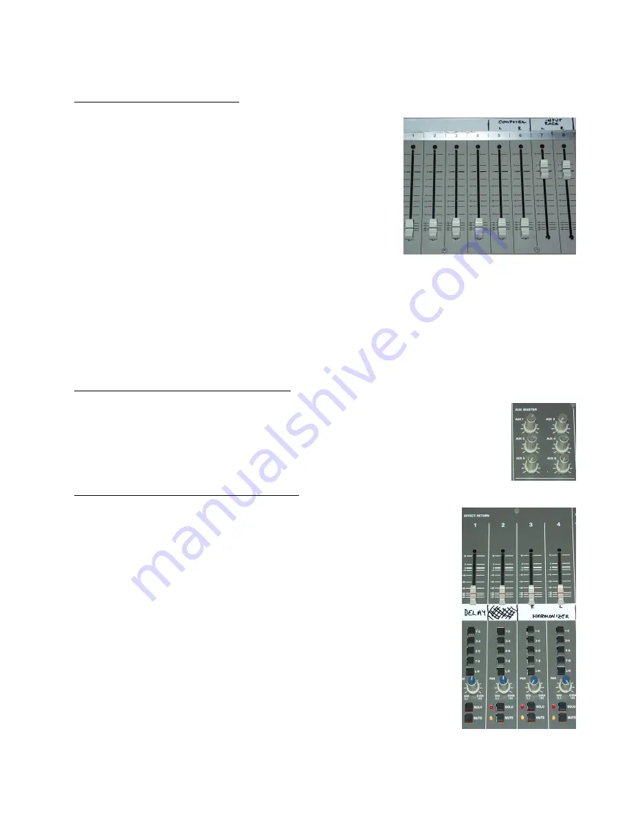
The FADERS allow easily adjustable control of the amplitude of
each individual channel. Based upon earlier “PRE” and “POST”
selections, this can effect other sections, such as the MONI-
TOR, AUX and BUS signals.
Each fader is marked to show the 0 dB level settings. To adjust
the input gain structure, each fader should be set to 0 dB and its
level should be adjusted using the INPUT level knob. This will
allow the best S/N ratio for each channel to continue to the final
output.
Figure 7
The following controls effect all channels, unless otherwise specified. These controls allow the
engineer to adjust CONTROL ROOM, STUDIO and STEREO INPUTS/OUTPUTS, as well as to
control the effects units.
MASTER AUXILARY SEND SECTION
While each channel may send a signal to the aux send, when they are all sent, the levels
may be excessive. This section allows the engineer to adjust the summed level to better
fit the effect unit. Each AUX SEND has an individual master control. If these levels
are not set, no sound may be sent to an effect unit.
MASTER EFFECTS RETURN SECTION
While there are 6 AUX SENDS, there are only 4 AUX RETURNS, or
EFFECTS RETURNS, each a mono, single signal source. EFFECT RE-
TURN 1 is the Lexicon multieffects unit. ER 2 is unused and ER 3 and 4 are
the stereo returns from the Eventide harmonizer. The faders allow adjust-
ment of each returns volume level. Each fader is marked to show the 0 dB
level settings. Adjust these levels as described above. The BUS buttons
work as in the OUTPUT section of the individual channels.
The “PAN” knob adjusts the levels sent to the output. In the center, it sends
equal amounts to the stereo pairs.
The “SOLO” button prevents all other channels from being sent to the head-
phone jack, to isolate each channel and, when engaged, lights the red LED
and the “SOLO” LED in the CONTROL ROOM section (See figure 10)..
The “MUTE” button stops all sends from this channel and, when engaged,
lights the yellow LED.
Figure 8
Figure 9


