TASCAM M-3500 MIXING CONSOLE
3
STUDIO MONITOR SECTION
Each channel has the capability of sending a copy of itself to the
Isolation Booth, otherwise known as the Studio. This can be
independant of the Control Room sound, or be a copy of it,
depending upon the settings of the monitor section.
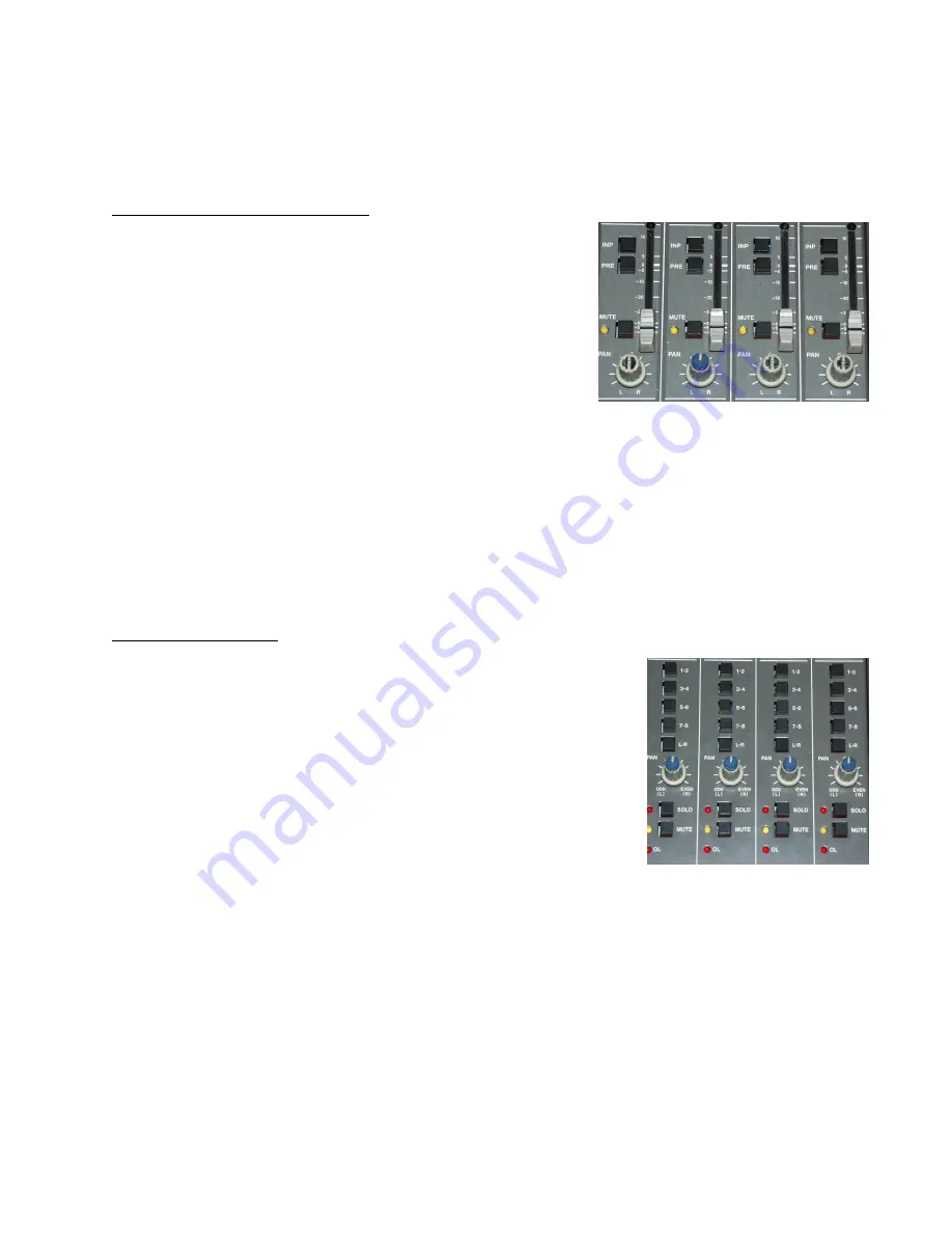
The “INP” button, when depressed, sends an exact copy of the
input section, without EQ or AUX sounds, to the Studio.
Figure 5
The “PRE” button, when depressed, uses this section to adjust the levels sent to the Studio. If it is
not depressed, the faders control the Studio volume of this channel.
The fader control adjusts the volume to the Studio when this section is used to adjust the Studio
volume seperate from the Stereo volume.
The “PAN” knob adjusts the left/right panning of this channel. The “MUTE” button stops all Studio
sends from this channel and, when engaged, lights the yellow LED.
OUTPUT SECTION
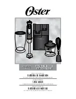
This is where each signal is split into two, stereo, pieces of signal
and assigned where it will go to next. The first four buttons can
send the channel to one of the 8 (eight) busses, for premixing.
Busses 1/2, 3/4, 5/6 and 7/8 act as stereo pairs. The “L-R” button
sends the channel directly to the left and right channels of the
Stereo Output. One of these buttons must be depressed or no
output from this channel will be heard.
The “PAN” knob adjusts the levels sent to the output. In the center,
it sends equal amounts to the stereo pairs.
The “SOLO” button prevents all other channels from being sent to the headphone jack, to isolate
each channel and, when engaged, lights the red LED and the “SOLO” LED in the CONTROL
ROOM section (See figure 10).. The “MUTE” button stops all Studio sends from this channel and,
when engaged, lights the yellow LED.
The “OL” LED lights whenever the final signal from this channel is clipped. It is advisable to adjust
all setting in such a way as to NOT light this LED. This is a different signal than that shown when the
“PEAK” LEDs are lit in the Main Meters (See figure 17).
Figure 6


