


14
TASCAM US-2x2/US-4x4
6 – Using the Settings Panel
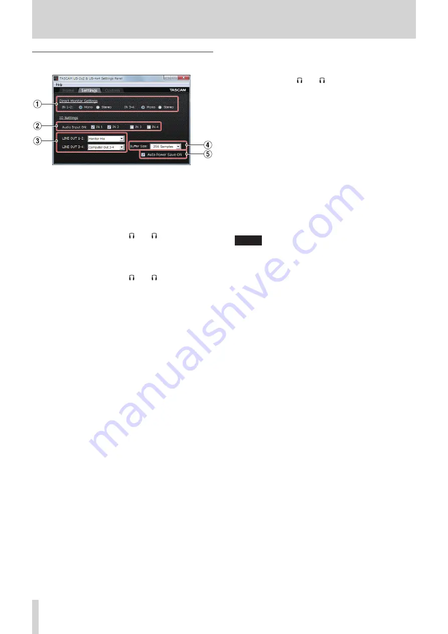
Settings page
1
Direct Monitor Settings
IN 1-2 and IN 3-4 (US-4x4 only)
Set the monitoring signal for the IN1-IN2/IN3-IN4 jacks to
“Mono” or “Stereo”.
o
When set to “Mono”
Stereo signals sent to the computer remain unchanged,
but are output as mono signals from the LINE OUT
(BALANCED) and PHONES ( 1 and 2 jacks on US-4x4)
jacks.
o
When set to “Stereo”
Stereo signals sent to the computer remain unchanged,
and are output as stereo signals from the LINE OUT
(BALANCED) and PHONES ( 1 and 2 jacks on US-4x4)
jacks.
2
Audio Input items
Turn input on/off for each channel separately.
i
Turn an input on by putting a check in its checkbox
.
When an input is on, signals on that channel will be
input.
i
Turn an input off by removing the check from its
checkbox
. When an input is off, signals on that
channel will not be input.
3
Line Outputs items
LINE OUT 1-2
i
Select the signals output from the unit’s LINE OUT 1-2
and PHONES ( 1 and 2 jacks on US-4x4) jacks.
LINE OUT 3-4 (US-4x4 only)
i
Select the signals output from the unit’s LINE OUT 3-4
jacks.
Options
“Monitor Mix”
The signals from the channels selected using the
Audio Input On/Off items and the signals sent from
the computer by USB are mixed using the MONITOR
BALANCE knob. This mix is output from the LINE OUT 1-2
and PHONES jacks.
“Computer Out 1-2”
Only the “Computer Out 1-2” signals sent from the
computer by USB are output from the LINE OUT
[BALANCED] and PHONES jacks.
”Computer Out 3-4 (US-4x4 only)“
Only the “Computer Out 3-4” signals sent from the
computer by USB are output from the LINE OUT
[BALANCED] and PHONES jacks.
NOTE
Set the
MONITOR BALANCE
knob all the way to the left
(INPUT)
to monitor only the input channel signals and set it
all the way to the right
(COMPUTER)
to monitor only signals
output from the computer. At other positions, both signals
will be mixed.
4
Buffer Size item
The driver for the unit stores the audio input and output
signals transferred to and from the computer temporarily in
a buffer.
This buffer size can be adjusted.
Smaller buffer sizes result in less audio signal delay (latency),
but require high-speed processing by the computer.
If the processing cannot keep up, for example, due to other
system operations, clicking and popping noises might occur
and the audio signal might even drop out.
Increasing the buffer size will stabilize operation and
suppress negative effects on audio signals, but the delay in
audio signals sent to the computer will increase.
You can use the slider on the panel to adjust the buffer size,
according to the use conditions.
You can adjust the buffer size used with this unit according to
your use conditions.
5
Auto Power Save ON
When this setting is on, if operating in standalone mode and
no input signal (above −60 dBFS) has been detected for 30
minutes, the unit will turn itself off (start standby) automati-
cally.
o
Putting a check (
4
) in the checkbox will turn the
automatic power saving function on so the unit will
automatically turn off (enter standby mode).
o
Removing the check (
4
) in the checkbox will turn the
automatic power saving function off.


