background image

010410-16 TC54.NG02.C

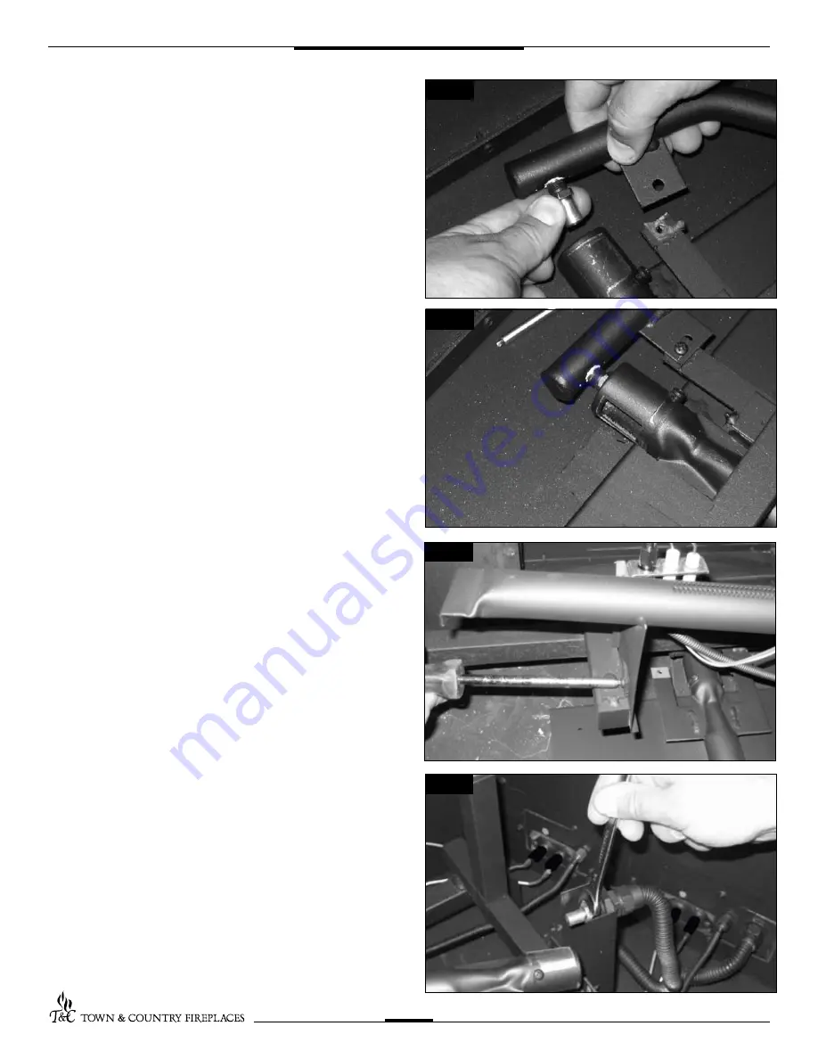
4.  Apply a small amount of pipe joint compound to the threads of 

the propane burner orifice (marked #

43) to ensure a good seal, 

before screwing it into the fitting. (Fig. #13)

5.  Open shutter fully. (Fig. #14)

6.   Reinstall the manifold to the lower burner using the screws previ-

ously removed.

7.   Remove the screw securing the upper burner to the grate 
 

assembly. (Fig. #15)

8.   Using a 1/2”  wrench, undo the natural gas burner orifice, (marked 

#28). (Fig. #16)

9.  Apply a small amount of pipe joint compound to the threads of 

the propane burner orifice (marked #

43) to ensure a good seal, 

before screwing it into the fitting.

10.  Open shutter fully.

11. Reinstall the upper burner to the grate assembly and secure in 

place using the screw previously removed.

Fig. #13

Fig. #14

Fig. #15

Fig. #16 

6

Содержание TC54.NG02.C

Страница 1: ...tions supplied with the fireplace and should be kept together Refer to the Installation and Operating Instructions for proper gas supply safety requirements and operating instructions TC54 COUNTRY HOM...

Страница 2: ...aside Place the keyhole slots in the burner over the two screws located in the firebox base Fig 1 1a b 1b Slide the burner back to engage the screws in the small part of the keyhole slot and tighten...

Страница 3: ...o the front electrical bulk head Fig 3 The spark electrode connection has a red dot above it Slide the insulation sleeve back onto the bulkhead connections Fig 4 Replace the ceramic fibre filler piece...

Страница 4: ...res coming from the upper burner pilot Attach spark electrode RED and sensor leads from upper burner pilot to the rear electrical bulk head Fig 9 The spark electrode connection has a red dot above it...

Страница 5: ...ervice agency is responsible for the proper installation of this kit The installation is not proper and complete until the operation of the converted appliance is checked as specified in the manufactu...

Страница 6: ...previ ously removed 7 Remove the screw securing the upper burner to the grate assembly Fig 15 8 Usinga1 2 wrench undothenaturalgasburnerorifice marked 28 Fig 16 9 Apply a small amount of pipe joint co...

Страница 7: ...ached to the lower burner assembly Fig 17 13 Slide the pilot adjustment band over and ensure that the hole in the orifice band is showing Fig 18 indicates NG position Fig 19 indicates LP position 14 R...

Страница 8: ...the conversion label Peel off the protective backing and apply the conversion label directly over the gas specifications on the rating label 22 Attach the access panel to the side of the firebox with...

Страница 9: ...l Gas Propane Minimum 5 0 wc 12 5 wc Maximum 13 9 wc 13 9 wc Manifold Pressure Maximum 3 4 wc 11 0 wc Minimum 1 8 wc 5 5 wc Note To test the gas pressure turn off the gas supply before removing the pl...

Страница 10: ...s leave it loose for best performance Fill the lower burner pan level with the top of the pan at rear and gradually slope forward to the firebox floor covering both lower burner tubes Place remaining...

Страница 11: ...icated by the following pictures The three main logs have holes and or pins Engage each pin in the corresponding holes The four smaller logs do not have holes or pins They rest in position Locate as p...

Страница 12: ...3 010410 16 TC54 NG02 C 3 2 1 4 5 7 6 Fig 33 Fig 34 Fig 35 5 6 12...

Страница 13: ...d stringy The shutter may also be opened to enhance the Ember Material glow and lessen the flame height Caution Burner area may be hot Turn off the fireplace and allow the unit to cool before proceedi...

Страница 14: ...4 LINE DORMONT 5019 225 9 FITTING ORIFICE INLET 5019 21 10 UPPER BURNER BRACKET 8187 5 11 1 2 14NPT BRASS LOCKNUT 5021 01 12 FLEX 1 2 LINE DORMONT 5019 223 13 BURNER TC54 REAR 5011 8302 LOG SET COMPL...

Страница 15: ...010410 16 TC54 NG02 C 15 Notes...

Страница 16: ...TECHNICAL SUPPORT 1 250 748 1184 www townandcountryfireplaces net 2975 Allenby Rd Duncan BC V9L 6V8 Printed in Canada...

Отзывы: