background image


The mounting bracket included with your camera provides convenient mounting to 

vertical surfaces, such as walls. The camera support platform can be tilted up or down to 

help point the camera toward your area of interest. You can also rotate the camera in 

any direction on the platform. 

Step 1

. Find a suitable location to mount the camera. 

Step 2

. Using the mounting bracket as a guide, mark the location of the two mounting 

holes. 

Step 3

. Drill a ¼” hole for each screw. 

Step 4

. Use a hammer to tap the two plastic anchors into the holes. 

Step 5

. Use the two screws to fasten the bracket to the wall. 

Step 6.

 Place the camera on the mounting bracket platform and rotate the camera to be 

facing in the desired direction. 


Step 7

. Secure the camera to the mounting bracket using the thumbscrew located on the 

bottom of the platform. 

Step 8

. Loosen the tilt adjust thumbscrew and tilt the camera toward the area to be 

observed. 


5 System 

Configuration 

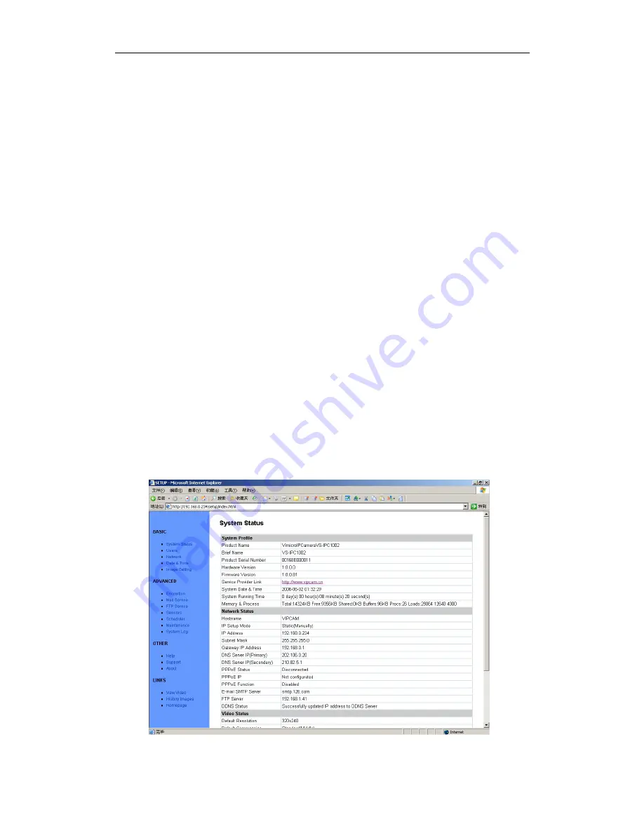
5.1 System status 

This page shows status of the system for diagnose.


Figure 21 System Status View 


- 17 -

Содержание V Series

Страница 1: ...1 V V S Se er ri ie es s I IP P C Ca am me er ra a U US SE ER R M MA AN NU UA AL L Version V1 0 Release ...

Страница 2: ...UNTING THE IP CAMERA 16 5 SYSTEM CONFIGURATION 17 5 1 SYSTEM STATUS 17 5 2 USER MANAGEMENT 18 5 3 NETWORK 19 5 4 DATE AND TIME 19 5 5 VIDEO 20 5 6 JPEG ENCRYPTION 20 5 7 E MAIL 22 5 8 FTP 23 5 9 SENSORS AND MOTION DETECTION 23 5 10 SCHEDULER TRIGGER 24 5 11 SYSTEM MAINTENANCE 24 5 12 SYSTEM LOG 25 5 13 GUEST ZONE 25 6 VISIT IP CAMERA OVER INTERNET 26 6 1 WAN IPADDRESS 26 6 2 NETWORK ADDRESS TRANSL...

Страница 3: ...3 Figure 17 IP Camera Home Page 14 Figure 18 Login Message box 14 Figure 19 Video webpage 15 Figure 20 History Images View 16 Figure 21 System Status View 17 Figure 22 User Management View 18 Figure 23 Network Setup View 19 Figure 24 Date and Time Setup View 19 Figure 25 Video Setup View 20 Figure 26 JPEG Encryption Setup View 20 Figure 27 Require Password Input in Client Web Browser 21 Figure 28 ...

Страница 4: ...o to your desktop from anywhere on your local network or over the Internet Your IP Camera package should contain the following items If any of the listed items are missing please contact your reseller from where you purchased the camera for assistance The package includes 9 IP Camera 1 9 IP Camera Utility CD 1 9 5V Power Adapter 1 9 Stand of plastic 1 9 1 5 meter cable 1 1 ...

Страница 5: ...dentify IP Camera Figure 1 IP Camera 45 angle View Lens Tilt Night Vision LEDs Pan Working Status LED Privacy Indicate LED User Visiting LED Privacy Status Button IP Show LCD Figure 2 IP Camera Front View 2 ...

Страница 6: ...RESET Button Figure 3 IP Camera Back View LED Privacy LED Working Button Privacy LED User Visiting LCD Figure 4 Front View Indication and Operation The privacy button toggles Privacy mode and Normal mode In Privacy mode all the remote users will not be allowed to see the video ...

Страница 7: ... Indications LCD will loop show IP Address Network Mask Gateway as shown in the Figure 6 IP Address 192 168 0 24 Subnet mask 255 255 255 0 Gateway IP 192 168 0 1 Figure 6 IP Address Network Mask Gateway loop show 4 ...

Страница 8: ...de indications Icon Meaning Static IP Use static manually fixed IP mode DHCP IP Address is dynamically assigned by DHCP Server PPPoE IP Camera s internal PPPoE dial function enabled Used for xDSL Working status LED meaning LED Status Meaning Normal Flashing Turns on for 1 2 second every 3 seconds Normal running Always on or always off System error Fast Flashing Turns on for 1 2 second every 1 seco...

Страница 9: ...w Indication Figure 8 Input Output defines CF Card Socket Reset button Input Output Pins RJ45 Ethernet Socket DC 5V Input Socket Output Pins Relay Normally Open Digit Input Pins 1 2 3 4 5 Output Input Common Input 1 2 A B ...

Страница 10: ...represented by Pin 1 and Pin 2 You may use it to control one external load below AC DC 36V 2 Amp While connecting input and output pins strip off the protect rubber of wire for 5mm the use a small screwdriver to depress and latch down the orange tabs over holes Insert the red wire into hole until the insulation just reaches the back of the camera use the screwdriver to press down and release the o...

Страница 11: ...ra please take a test before purchase RESET button Click the reset button shortly will reboot the system If you press the button and hold for 5 seconds or longer the system will restore to factory default configuration it will take about 30 seconds then reboot automatically Caution DO NOT switch off IP Camera s power during the procedure of restoring factory default It will take about 30 seconds 2...

Страница 12: ...128 bit AES encryption to the images transportation ensures your information security 9 Digital Video Recording and Transportation IP Camera can store images to CF Card or send images to your mailbox when triggered 9 Motion Detection Your may use the internal Motion Detection function or external PIR sensor to trigger images recording and transportation 9 Relay Output Control The internal relay ca...

Страница 13: ...ill make accessing from the Internet much more convenient 4 Setup Procedure Before use IP Camera please setup according to the following procedures 4 1 IP Camera Power Network Connection Plug the included Ethernet cable into the RJ 45 connector at the back of the camera as shown Figure 11 Connecting the Ethernet wire Connect the power supply to the back of the camera as shown and then plug the sup...

Страница 14: ...connection is shown below The LED of LAN port will then turns ON CAUTION Make sure to only use the power adapter supplied with your IP Camera Using a non approved power adapter may damage the camera In different country or region the power supply might be different 110V 220 50Hz 60Hz please make sure it correspond to the tag marked on the power adapter Figure 13 LAN connection 11 ...

Страница 15: ... 234 Note IP Camera by default use fixed static IP address setting The default IP address is 192 168 0 234 Network Mask is 255 255 255 0 Gateway is 192 168 0 1 4 3 Use IPCamSearch Tool to setup IP Cameras Put the supplied CD into your CDROM Click and run IPCamSearch exe Tool Figure 14 IP Camera Search Tool This tool shows all IP Cameras found on your LAN with its Serial Number IP Address Firmware ...

Страница 16: ... username and password to continue Figure 16 Input Administrator s Username and Password Note By default administrator s username is admin password is 123456 Input the correct username and password and click OK then you can see a message box indicating IP Camera s IP Address has changed IP Camera is in static IP mode now Then you may click Visit IPCam to run an Internet Explorer You can do more co...

Страница 17: ...s front LCD Then you can input IP Camera s IP Address into IE s address bar to access 4 4 View Video on Web Browser You may visit IP Camera s homepage by IE or other compatible web browsers Figure 17 IP Camera Home Page Click User Visit to view video You will see a message box which requires your login as shown below Figure 18 Login Message box 14 ...

Страница 18: ... return to home position Note Do not cruise long time continually On the left you can also select the Resolution Quality Brightness Contrast and Zoom Resolution can be 640x480 320x240 and 160x120 The higher resolution the higher clarity while requiring more bandwidth Quality can be High Standard or Low High consumes largest bandwidth thus the frame per second will down If you feel the frame per se...

Страница 19: ...era The IP Camera can sit on a flat surface such a shelf or bookcase be mounted to a wall using the included bracket or mounted atop a tripod stand using the standard tripod mount located on the underside of the base When using the camera free standing be sure to secure the cables Failing to secure the cables could cause the camera to be pulled off the mounting surface resulting in damage to the c...

Страница 20: ...nting holes Step 3 Drill a hole for each screw Step 4 Use a hammer to tap the two plastic anchors into the holes Step 5 Use the two screws to fasten the bracket to the wall Step 6 Place the camera on the mounting bracket platform and rotate the camera to be facing in the desired direction Step 7 Secure the camera to the mounting bracket using the thumbscrew located on the bottom of the platform St...

Страница 21: ...to all the sections User This permission level allows the user access to IP Camera menus but without the permission to setup Guest This permission level allows the user to access IP Camera s video only The user does not have any permission to change disabled Make the user account disable no access Allow Anybody Visit IP Camera provide a Guest Zone if you checked this any temporally visitors may en...

Страница 22: ...5 3 Network Figure 23 Network Setup View 5 4 Date and Time Figure 24 Date and Time Setup View 19 ...

Страница 23: ...5 5 Video Figure 25 Video Setup View 5 6 JPEG Encryption Figure 26 JPEG Encryption Setup View 20 ...

Страница 24: ...Figure 27 Require Password Input in Client Web Browser Figure 28 Input Password in Web Browser ActiveX Figure 29 Input Password in Web Browser Java 21 ...

Страница 25: ... features SMTP Server The administrator will have to enter the Email server address here Sender s Email This will determines IP Camera s Email address Email Requires Authentication If checked the administrator will have to provide the account name and password in order to access the Email server E mail Sender Username Enter the account name or login name to the Email server E mail Sender Password ...

Страница 26: ...5 8 FTP Figure 31 FTP Setup View 5 9 Sensors and Motion Detection Figure 32 Sensors and Motion Detection Setup View 23 ...

Страница 27: ...5 10 Scheduler Trigger Figure 33 Scheduler Trigger Setup View 5 11 System Maintenance Figure 34 System Maintenance View 24 ...

Страница 28: ...5 12 System Log Figure 35 System Log View 5 13 Guest Zone Figure 36 Guest Zone View 25 ...

Страница 29: ...vice Provider grants you through a high speed br connection you can access your cameras by web browser from anywhere on the Internet To do this you need to 1 Know your WAN Internet Service Provider gives you to access the Internet It may be static always the same or dynamic can change from time to time Make sure the port used by the camera 80 to the camera Make sure your router gateway 6 1 W The W...

Страница 30: ... Also any time you reboot your cable or DSL modem your are likely to get a new address when reconnecting The solution to the ever changing IP address is known as DDNS or dynamic domain name service A DDNS will allow you to find your network by a domain name such as http tom vipcam cn rather than needing to know the IP address 6 2 Network Most home routers and business firewalls today perform Netwo...

Страница 31: ...uter H be sure that you have set the correct gateway IP address in order to connect your camera to the Internet Note It may not be possible to test WAN Internet access to your cameras from a PC connected to the LAN To be sure that your cameras are accessible by the Internet you should contact someone you know with Internet access preferable broadband and have them enter your WAN IP address into th...

Страница 32: ...a access Therefore you should use port 81 for your first camera port 82 for the second etc This setup also makes it easier to remember which camera is using a particular port number 6 6 Your Internet Service Provider ISP provides you at least one IP addr to connect to the Internet The address you get may be static meaning it never changes or dynamic meaning it s likely to change periodically Just ...

Страница 33: ...D automatically when your IP address changes Please consult your router s documentation for more information If your router does not support DDNS you can setup the IP Camera s DDNS client 6 7 Configuration Example A same IP Sharing Device Gateway Router Address by ISP e g 210 82 13 21 while LAN IP e g 192 168 0 151 192 168 0 10 192 168 0 11 k Envi ery LAN device connect to INT ET via NAT fun ow ma...

Страница 34: ...first DMZ Host function will disable all Virtual Server function s Address e g 192 168 0 151 s 6 ve P era can be accessed in WAN 7 2 In WAN configura your ISP 3 Click Advanced on T 4 Click Virtual Server Note If you use Virtual Server mode you must turn DMZ host functio 5 Input the following information on page Enabled Disabled Enabled Name VilarCamera Private IP Input IP Camera Protocol Type TCP ...

Страница 35: ...y Relay Output 36V AC DC 2A Connection 5 Pins Network Interface Ethernet 10 100Base T RJ 45 Transport RTP IP UDP IP TCP IP SMTP HTTP FTP Protocol Other DNS and DHCP client DDNS Power Supply 5V DC Consumption 5W Maximum Physical Temperature 0 45 Humidity 50 95 Management System Setup Web Page Upgrade Firmware upgrade by Web Other CPU 32bit ARM 66MHz frequency SDRAM 16MByte FLASH 4MByte 32 ...

Отзывы: