Alarm memory
External control switch
Transmitter
Transmitter
Receiver
Transmitter
Receiver
Power supply
(12 V DC)
Alarm signal
(N.C.)
Power supply
(12 V DC)
Power supply
(12 V DC)
Alarm signal
(N.C.)
Power supply
(12 V DC)
Alarm signal
(N.C.)
Receiver
(When short circuit occurs: display)
Environment signal (N.C.)
(Controller)
(Controller)
(Controller)
(Controller)
(Controller)
(1CH)
(1CH)
(3CH)
(3CH)
(1CH)
(3CH)
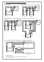
WIRING DISTRIBUTION DIAGRAM (WIRING DIAGRAM)
5-3
Basic connections
When multiple sensor units are connected to the same circuit
Basic connections for 2 level protection
For environmental output, tamper output, and alarm memory display in the remote mode
When multiple sensor units are connected to separate
circuits
[Precautions for Installation]
(1) Signal output for the upper and lower levels of the receiver cannot be output separately.
(2) For outdoor wiring installation, carry out pipe laying work whenever possible.
(3) Never use overhead wiring.
Transmitter
Transmitter
Transmitter
Transmitter
Transmitter
Receiver
Receiver
Receiver
Receiver
Receiver
Alarm signal 1
(N.C.)
Alarm signal 2
(N.C.)
Power supply (12 V DC)
Alarm signal (N.C.)
Auto gain lock control (N.O.)


