


11
SPECIFICATIONS
10
TROUBLESHOOTING
12
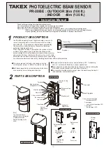
EXTERNAL DIMENSIONS
196mm (7.72”)
4) Protection distance exceeds 40m. (30m outdoor)
4) Keep protection distance within 40m. (30m outdoor)
Symptom
Possible cause
Remedy
1) No power supply.
2) Bad wiring connection or broken wire, short.
3) Beam is reflected on another object and sent into the receiver.
1) Turn on the power supply.
2) Check wiring.
3) Remove the reflecting object or change beam direction
Alarm LED does not light
when the beam is broken.
Alarm LED continues to
light.
1) Beam alignment is incorrect.
2) Shading object between sensor and reflector.
3) Sensor cover or refrector are soiled.
1) Check and adjust again.
2) Remove the shading object.
3) Clean the reflector with a soft cloth, or wash the cover water.
1) Bad wiring connection.
2) Unstable supply voltage.
3) Shading object between sensor and reflector.
4) A large electric noise source such as power machine is located
nearby sensor.
5) Unstable installation of sensor and reflector.
6) Sensor cover or refrector are soiled.
7) Improper alignment.
8) Big birds may pass through the beams.
1) Check again.
2) Stabilize supply voltage.
3) Remove the shading object.
4) Change the place for installation.
5) Stabilize the installation.
6) Clean the reflector with a soft cloth, or wash the cover water.
7) Check and adjust again.
8) Set the response time longer. (Do not use this setting
where an intruder can run at full speed through the beam.)
Intermittent alarm
Knockout
Knockout
□
12mm
×
7mm
(
□
0.47"
×
0.28")
(
□
0.47"
×
0.28")
□
12mm
×
7mm
2-
φ
0.16"(
φ
4)
Wiring lead
20mm(0.79")
83.5mm
(3.29"
)
14.5mm
(0.57"
)
44mm
(1.73"
)
12mm
(0.47")
73mm(2.87")
71.5mm(2.81")
25mm
(0.98")
170mm (6.69")
Model
Detection system
Protection distance
Supply voltage
Current consumption
Alarm output
Tamper output
Response time
Alarm LED
Functions
Ambient temperature range
Mounting positions
Wiring
Weight
Appearance
PR-30BE
Outdoor 1.7 to 100' (0.5 to 30m)
Indoor 1.7 to 135' (0.5 to 40m)
10.5V to 30V DC (Non-polarity)
(Class 2 powered device)
200 mA or less
160 mA or less (12V DC)
80 mA or less (24V DC)
Dry contact relay
Contact capacity : 30V (AC/DC) 0.25A or less
Relay operation : Interruption time (minimum 2 secs)
Dry contact relay
Contact capacity : 30V (AC/DC) 0.25A or less
Dry contact relay 1b (N/C)
Action : Activated when cover is detached.
Contact capacity : 30V (AC/DC) 0.25A or less
0.05 / 0.1 / 0.25 / 0.5sec.
Red LED ON : when an alarm is initiated
Red LED
・Monitor output
-13
°
F to +140
°
F (-25
℃
to +60
℃
)
Outdoor/Indoor
Terminals
Sensor : Resin (wine red)
Reflector : Resin (clear / black)
REFLECTOR
SENSOR
*
Do not clean the cover with a cloth.
〈
Daily check
〉
〜〜〜〜〜〜〜〜〜〜〜〜〜〜〜〜〜〜〜〜〜〜〜〜
*
Do not clean the cover with a cloth.
〜〜〜〜〜〜〜〜〜〜〜〜〜〜〜〜〜〜〜〜〜〜〜〜
Check the operation of the unit once a week. If the cover becomes soiled, wash it with water.
Never clean it with a cloth otherwise it could damage the photocatalytic coating applied to the sensor cover.
The coating is designed to prevent attenuation of the infrared caused by waterdrops from torrential rain.
〜〜〜〜〜〜〜〜〜〜〜〜〜〜〜〜〜〜
3-0.16” (
φ
4)
19.5mm(0.77”)
100mm(3.94”)
93mm(3.66”)
226mm (8.90”)
126.8mm (4.99”)
58mm
(2.28”)
101mm(3.98”)
6mm
(0.24”
)
Center of the reflector
Environmental output
Sensor : 13oz (370g) Reflector : 6.7oz (190g)
Dry contact relay N.O. /N.C.
Dry contact relay N.O. /N.C.
Sensitivity attenuation
/Environment LED
When front cover detached (when alignment) :
Beam is attenuated.
When front cover attached : Weather condition
gets worse. (Synchronize with Env.output)
・Response time adjustment
⑧
Limited Warranty :
TAKEX products are warranted to be free from defects in material and workmanship for
12 months from original date of shipment. Our warranty does not cover damage or
failure caused by natural disasters, abuse, misuse, abnormal usage, faulty installation,
improper maintenance or any repairs other than those provided by TAKEX. All implied
warranties with respect to TAKEX, including implied warranties for merchantability and implied warranties for fitness, are limited in duration to 12 months from original date of
shipment. During the Warranty Period, TAKEX will repair or replace, at its sole option,free of charge, any defective parts returned prepaid. Please provide the model number of the
products, original date of shipment and nature of difficulty being experienced. There will be charges rendered for product repairs made after our Warranty Period has expired.
In Japan
Takex America Inc.
Takenaka Engineering Co., Ltd.
https : // www. takex-eng. co. jp /
Takex America Inc.
https : // www. takex. com
Takex Europe Ltd.
https : // www. takex. com
In the U.S.
In the U.K.
In Australia
Aviary Court, Wade Road,
Basingstoke, Hampshire. RG24 8PE, U.K.
Tel : (+44) 01256-475555
Fax : (+44) 01256-466268
4/15 Howleys R oad, Notting Hill,
VIC, 3168
Tel : +61 (03) 9544-2477
Fax : +61 (03) 9543-2342
https : // www. takex. com
83-1, Gojo-Dori, Sotokan Nishi-iru, Higashino,
Yamashina-ku, Kyoto 607-8156, Japan
Tel : 81-75-501-6651
Fax : 81-75-593-3816
151, San Zeno WAY
Sunnyvale, CA 94086, USA
Tel : 408-747-0100
Fax : 408-734-1100
*Specifications are subject to change without notice.
<Caution>
The suitability of this device with respect to reducing casualty hazards or providing a
safety function is to be determined in the end-use application.
Near infrared beam interruption system (reflective)
Unit : mm (inch)


