⑦
21 (QDEOHVOLJKWLQJ
2))/LJKWLVDOZD\VRII
,QGLFDWHVDEQRUPDORXWSXWRQO\
',3VZLWFK
21
2))
)DFWRU\VHW
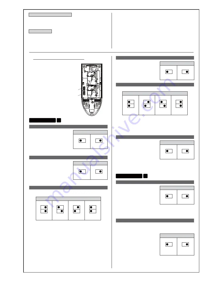
Alarm LED setting (1 of mode selector 1)
Sets the alarm LED (red) to light
on/off.
21 (QDEOHG
6HWVWKHOLJKWLQJRSHUDWLRQ
SDWWHUQDWRIPRGHVHOHFWRU
2))'LVDEOHG
Sets the memory function to be
enabled/disabled.
Memory function setting (2 of mode selector 1)
',3VZLWFK
21
2))
)DFWRU\VHW
Use the mode selectors 1 and 2 inside
the sensor unit for various settings.
0RGHVHOHFWRU
0RGHVHOHFWRU
Temperature compensation
This function is used to automatically adjust the detection
sensitivity based on the temperature around the sensor.
Anti-masking
Sensitivity setting (3 of mode selector 1, 4 of mode selector 1)
21
2))
21
2))
21
2))
21
2))
%
%
)DFWRU\VHW
%
%
',3VZLWFK
Sets detection sensitivity.
>@ 6HOHFWWKLVRSWLRQZKHQWKHWHPSHUDWXUHRIGHWHFWLRQWDUJHWVLV
ORZRUWKHWHPSHUDWXUHGLIIHUHQFHEHWZHHQWKHEDFNJURXQGDQG
WKHWDUJHWVEHFRPHVVPDOOIRUH[DPSOHLQVXPPHU
>@ )DFWRU\GHIDXOWVHWWLQJ
>@
6HOHFWWKLVRSWLRQZKHQKHDWVRXUFHVEHVLGHVGHWHFWLRQWDUJHWV
DUHRIWHQGHWHFWHGZLWKWKHVHQVLWLYLW\VHRZHYHULI
WKHWHPSHUDWXUHGLIIHUHQFHEHWZHHQGHWHFWLRQWDUJHWVDQGWKH
EDFNJURXQGLVVPDOOWKH\PD\QRWEHGHWHFWHG0DNHVXUHWR
FKHFNLIGHWHFWLRQWDUJHWVFDQEHGHWHFWHG
>@
6HOHFWWKLVRSWLRQZKHQKHDWVRXUFHVEHVLGHVGHWHFWLRQWDUJHWV
DUHRIWHQGHWHFWHGZLWKWKHVHQVLWLYLW\VHRZHYHULI
WKHWHPSHUDWXUHGLIIHUHQFHEHWZHHQGHWHFWLRQWDUJHWVDQGWKH
EDFNJURXQGLVVPDOOWKH\PD\QRWEHGHWHFWHG0DNHVXUHWR
FKHFNLIGHWHFWLRQWDUJHWVFDQEHGHWHFWHG
21 (QDEOHG
2))'LVDEOHG
',3VZLWFK
21
2))
)DFWRU\VHW
Environmental adjustment setting (5 of mode selector 1)
Sets when false operations
frequently occur.
Mode selector 1
■
Description of mode selector
21 :KHQWKHVHQVRUWULJJHUVDQ
DODUPWKHPHPRU\/('EOLQNV
IRUPLQXWHVDQGOLJKWVIRU
PLQXWHVWKHQWKHOLJKWJRHVRII
:KHQWKHVHQVRUWULJJHUVDQ
DODUPDJDLQGXULQJOLJKWLQJWKH
WLPHUZLOOEHWULJJHUHGDQGWKH
/('ZLOOVWD\OLWIRUDIXUWKHU
PLQXWHV
2)):KHQWKHVHQVRUWULJJHUVDQDODUPWKHPHPRU\/('EOLQNVIRU
PLQXWHVDQGWKHOLJKWJRHVRII:KHQWKHVHQVRUWULJJHUVDQDODUP
DJDLQGXULQJEOLQNLQJWKHWLPHUZLOOEHWULJJHUHGDQGWKH/('ZLOO
FRQWLQXHWREOLQNIRUDIXUWKHUPLQXWHV
21
%OLQNLQJ
↓
/LJKWLQJXS
2))
%OLQNLQJ
)DFWRU\VHW
',3VZLWFK
Memory LED operation setting (2 of mode selector 2)
This setting is used to set the blinking operation of the memory
LED (red). This can be set only when DIP switch 2 of mode
selector 1 [memory LED setting] is ON.
Operation mode setting (6 and 7 of mode selector 1)
21
2))
21
2))
21
2))
21
2))
/RZSRVLWLRQPRGH
)DFWRU\VHW
+LJKGHQVLW\PRGH
+LJKSRVLWLRQPRGH
',3VZLWFK
0LGGOHSRVLWLRQPRGH
Sets based on the sensor operation mode.
/RZSRVLWLRQPRGH
6HOHFWZKHQWKHLQVWDOODWLRQKHLJKWLVWRP
·
WR
·
0LGGOHSRVLWLRQPRGH6HOHFWZKHQWKHLQVWDOODWLRQKHLJKWLVWRP
·
WR
·
+LJKSRVLWLRQPRGH 6HOHFWZKHQWKHLQVWDOODWLRQKHLJKWLVWRP
·
WR
·
+LJKGHQVLW\PRGH 6HOHFWZKHQWKHLQVWDOODWLRQKHLJKWLVKLJKRU\RXQHHGWR
GHWHFWREMHFWVPRUHDFFXUDWHO\
)DOVHDODUPPD\LQFUHDVHIRURXWGRRUXVH
21 (QDEOHG
2))'LVDEOHG
',3VZLWFK
21
2))
)DFWRU\VHW
Creep zone detection setting (8 of mode selector 1)
This setting can be used to detect
objects passing in the area
directly beneath the walls. Note
that pet immunity performance
decreases when this setting is
enabled. In the specialised
operation (high density mode),
this setting is disabled.
21 (QDEOHG
2))'LVDEOHG
',3VZLWFK
21
2))
)DFWRU\VHW
Walk test setting (1 of mode selector 2)
This setting is used to light up
only for a certain period of time
even if the alarm function setting
(switch 1-1) is disabled. Lighting
can be turned ON while the power
timer (during warming-up) is on
and the following 5 minutes, and
for 5 minutes after the cover is closed.
Mode selector 2
This function is used to warn against any attempt to
circumvent detection such as placing a shielding material
over the cover unit. When the masking of the cover unit is
detected after a certain time (30~60sec.), the anti-masking
alarm will output and alarm LED indicator is lit.
Check the surface and inside of the sensor unit to confirm that
there are no masking objects in front of the sensor and that the
sensor operates normally.
After ten seconds following removal of shielding material,
anti-masking alarm stops and the sensor recovers after alarm is
activated twice.
After replacement of the cover, or during the warming up period,
the anti-masking alarm is not output for a certain period of time.
If objects such as blot or insect become attached to the surface of
cover, the anti-masking alarm may be activated.
Please note that certain shielding material may not be detected
such as clear spray, or material with low reflectivity to
near-infrared.


