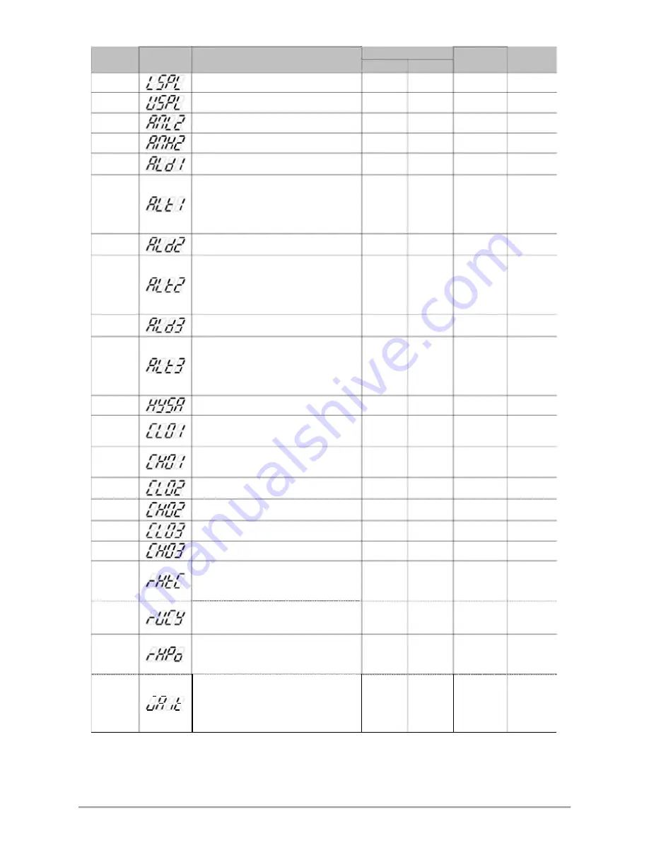
10.9 LEVEL_3 Parameter
t
n
e
t
n
o
C
l
o
b
m
y
S
r
e
t
e
m
a
r
a
P
Range
Default
Hide/
MAX
MIN
Display
LSPL
Input scale low
9999
-1999
---
SET2.3
USPL
Input scale high
9999
-1999
---
SET2.3
ANL2
Sub input zero calibration
9999
-1999
0
SET2.4
ANH2
Sub input span calibration (hex display)
0x7FFF
0x0000
0x5FFF
SET2.4
ALD1
Alarm1 mode selection
19
0
11
SET3.1
(Please refer to Chapter 12.1 Alarm Mode)
Alarm1 time setting
0.00
:
Flicker
ALT1
99.59
:
Continued ON
99.59
0.00
99.59
SET3.2
0.01~99.58
:
delay time
Time format
:
min . sec
ALD2
Alarm2 mode selection
19
0
0
SET3.3
(Please refer to Chapter 12.1 Alarm Mode)
Alarm2 time setting
0.00
:
Flicker
ALT2
99.59
:
Continued ON
99.59
0.00
99.59
SET3.4
0.01~99.58
:
delay time
Time format
:
min . sec
ALD3
Alarm3 mode selection
18
0
0
SET4.1
(Please refer to Chapter 12.1 Alarm Mode)
Alarm3 time setting
0.00
:
Flicker
ALT3
99.59
:
Continued ON
99.59
0.00
99.59
SET4.2
0.01~99.58
:
delay time
Time format
:
min . sec
HYSA
Hysteresis setting for alarm1~3
100.0
-100.0
1.0
SET4.3
CLO1
Main output zero calibration
only for linear signal
9999
0
0
SET4.4
(Please refer to Chapter 14.5)
CHO1
Main output span calibration
only for linear signal
9999
0
3600
SET4.4
(Please refer to Chapter 14.5)
CLO2
Sub output zero calibration
9999
0
0
SET5.1
only for linear signal
CHO2
Sub output span calibration
9999
0
3600
SET5.1
only for linear signal
CLO3
Retransmission zero calibration
9999
0
0
SET5.2
CHO3
Retransmission span calibration
9999
0
3600
SET5.2
Dehumidification temperature
*RHTC
If PV less than RHTC manipulated value =
200.0
0.0
0.5
SET5.3
RHPO
(Please refer to Chapter 11.5)
Motor valve operating time
RUCY
Time unit
:
second
150
5
5
SET5.3
(Please refer to Chapter 11.6)
Dehumidification manipulated value
*RHPO
0 : OFF disable dehumidification function
100.0
OFF
OFF
SET5.3
Other values : 0.1~100.0 manipulated value
(Please refer to Chapter 11.5)
Program execution standby temperature
0 : when program executed reach SV do not
WAIT
waiting for PV temperature
100.0
0
0
SET5.3
Other values : when PV= (target SV-WAIT),
program entering next segment
(Please refer to Chapter 13)
* Automatically display corresponding parameters according to different setting conditions
EX1: when OUTY= 3(motor valve drive) original RHTC will become RUCY display
EX2: when PROG= ON(program type) original RHPO will become WAIT display
FY/FU operation manual
26


