


XT-1/XT Mini Manual
13-111 05, 2015-08-14
Page 14 of 32
t
SU
t
PI
t
PW
t
H
t
R
t
F
CL
D0
D1
≈
≈
≈
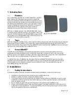
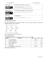
Figure 12 Wiegand timing diagram
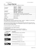
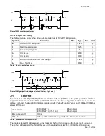
3.3.2 Magstripe Timing
The following values apply when all outputs are pulled up to 5 V with 1 k
Ω
resistors.
Symbol
Parameter
Min
Typ
Max
Unit
t
SU
LOAD to CLK setup time
1520
µ
s
t
F
Fall time (all signals)
125
ns
t
R
Rise time (all signals)
5
µ
s
t
CL
Clock low
480
µ
s
t
CH
Clock high
960
µ
s
t
H
LOAD hold time after last CLK change
1520
µ
s
t
DH
Data hold time
880
µ
s
Table 7 Magstripe interface timing
≈
≈
t
SU
LOAD
CLK
DATA
≈
t
CL
t
CH
t
DH
t
H
t
R
t
F
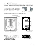
Figure 13 Magstripe timing diagram (note: data low = logic one)
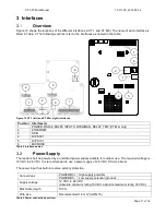
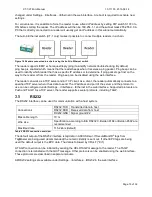
Ethernet
The reader has a 10 Mbps/100 Mbps Ethernet interface with one (XT Mini) or two (XT-1) ports. The interface
supports auto crossover (Auto-MDIX) so that installation can be done using either patch cables or crossover
cables. Each port has two LED indicators for Link/Activity (Yellow/Flashing Yellow) and 10 Mbps/100 Mbps
speed (Off/Green).
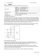
Connections
ETHERNET:A
Ethernet port
ETHERNET:B (XT -1 only)
Ethernet port
Max cable length
100 m
Wire size
CAT5e cable or better is required for the Ethernet connection
Table 8 Ethernet connection overview
The reader's default IP address and subnet mask can be found on a label on the backside of the reader.
The default address is on the format 10.x.x.x and the subnet mask is 255.0.0.0. All IP settings can be
Содержание XT Mini
Страница 1: ...XT 1 XT Mini Manual ...