6
Front Panel - PC Card
(PCMCIA)
Reader
The 2000I-DP is equipped with a Fortezza compliant PC Card reader located on
the front panel. TAG has configured the reader with SCSI #3. Refer to page 10 for all
SCSI IDs. The reader contains two slots which is designed to accept Type I, Type II,
and Type III card types. The upper card slot accepts only Type I and Type II cards. If a
Type III card is placed in the lower card slot of either PC Card reader, the upper slot is
not available.
The PC Card reader is equipped with four LED indicators and two card eject
buttons, (See
Figure 7).
The upper card eject button is on the left side of the slots
and the lower card eject button is on the right side of the slots.
The green LED on the left side of the unit indicates power is being supplied to that
unit. The red LED, positioned below the power indicator, will illuminate for one of
the following three reasons:
•
No card is inserted. When a card is inserted correctly, the red LED turnsoff.
•
A slot is accessed in which no card is inserted. The red LED remains lit until the
card in the other slot is accessed.
•
A card is inserted, but it cannot be accessed by the PC Card reader. This error can
have various causes; for example, the unit is attempting to write data to a write-
protected, a read-only, or an unknown I/O card or a hardware error exists on the
card.
The amber LEDs, on the right side of the PC Card reader, are the access indicators
for the upper and lower slots. The LED will illuminate when there is data activity on
the PC Card bus.
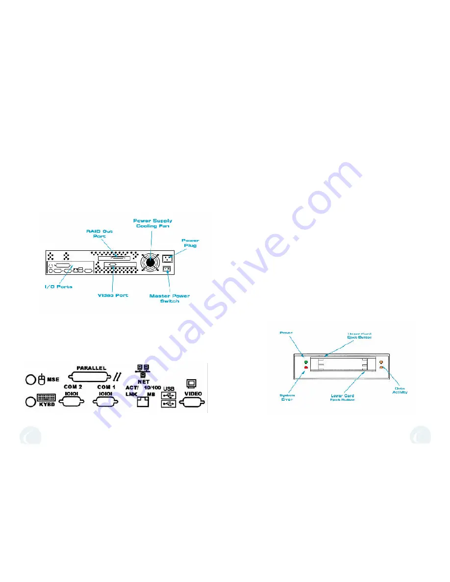
2000I-DP Rear Panel
The connectors for all of the external peripherals are located on the left side
of the rear panel of the 2000I-DP,
(See Figures 14 & 15)
. When connecting
peripherals, make sure the connectors are well seated in the port.
The main system power switch is located below the power supply on the
right side
(See Figures 14 & 16)
. Refer to page 7 for more information regarding
the power supply. When mounting both the 2000I-DP and the HDIT-108R into a
rack, please make sure all connections are secured in their appropriate ports
before sliding the unit into the rack.
3
Figure 7
Figure 14
Figure 15


