6
SECTION #4 LOADING OF LABELS CONTINUED:
3) Verifying that the labels are feeding off the bottom of the roll, take the leading edge of the labels and bring it
over A-10 Tension Roller and then in between Roller #3 and the Urethane Wiper. There is a thumb screw that
will allow the Urethane Wiper to swivel out of the way, but once the labels are past this point, replace the
Urethane Wiper to its original position.
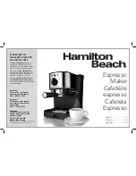
4) Continue feeding the leading edge of the labels to the Stop Sensor (A-3) and in between the 2 halves of the
sensor. This sensor will read the gap in between the labels and determine when the feed portion of the cycle
should stop.
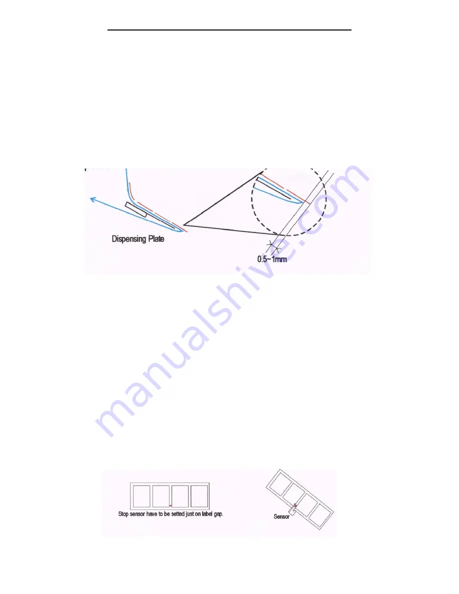
5) Feed the leading edge of the labels behind roller #4 on Figure #4 and then under the Urethane Wiper and around
the Dispensing Plate A-6. At this point pull off about 18 inches of the labels from the roll and feed it around the
Dispensing Plate so that 0.5mm to 1mm of a label is beyond the edge of the Dispensing Plate per Figure 5.
6) Making sure that the Black Handle located between the Press Rollers #5 and #6 on Figure #4, is in the open
position, bring the leading edge of the labels up and over the purple neoprene roller #5 into the space between
rollers #5 and #6 and then under roller #6.
7) Continue feeding the labels around #7 as per Figure #4 and then using the U-Clip secure the labels to the
Re-winder (A-9).
8) At this point, locate the Stop Sensor (A-3) and note that the Stop Sensor is mounted to a rail which allows for the
height of the Stop Sensor to be Adjusted. Loosening the screw, adjust the height of the Stop Sensor so that the
gap in the label is located in the middle of the Stop Sensor per Figure #6.
9) At this point, put the Black Handle located between Rollers #5 and #6 to the closed position.
10) The machine is now fed and ready for use.
Figure #5
Figure #6
Содержание Mini-Con
Страница 12: ...12 SECTION 9 PARTS LIST...


