User Manual 9260
2-6 Portrayal
Field Configuration
of the 9260 Settings
Limited flexibility is available for you, as the user, to change 9260
configuration in the field. Changing configuration involves the opening
of the top cover and therefore, it is suggested that this operation be
completely avoided or, if absolutely necessary, should be carried out
by factory-trained person.
Use the following instructions to re-configure 9260 settings in the field:
Remove the Top Cover
There are four screws bolting the top cover to the case. These are
located on both sides of the cover. Identify and remove these screws.
Use Philips screwdriver only to remove the screws. Hold the cover
from both sides and pull upwards until the top is clear of the case
sides. Once the top cover is open, you’ll be able to access jumpers
that set the different configuration.
Configure the Input Impedance
Before you change the 9260 input impedance settings, identify first
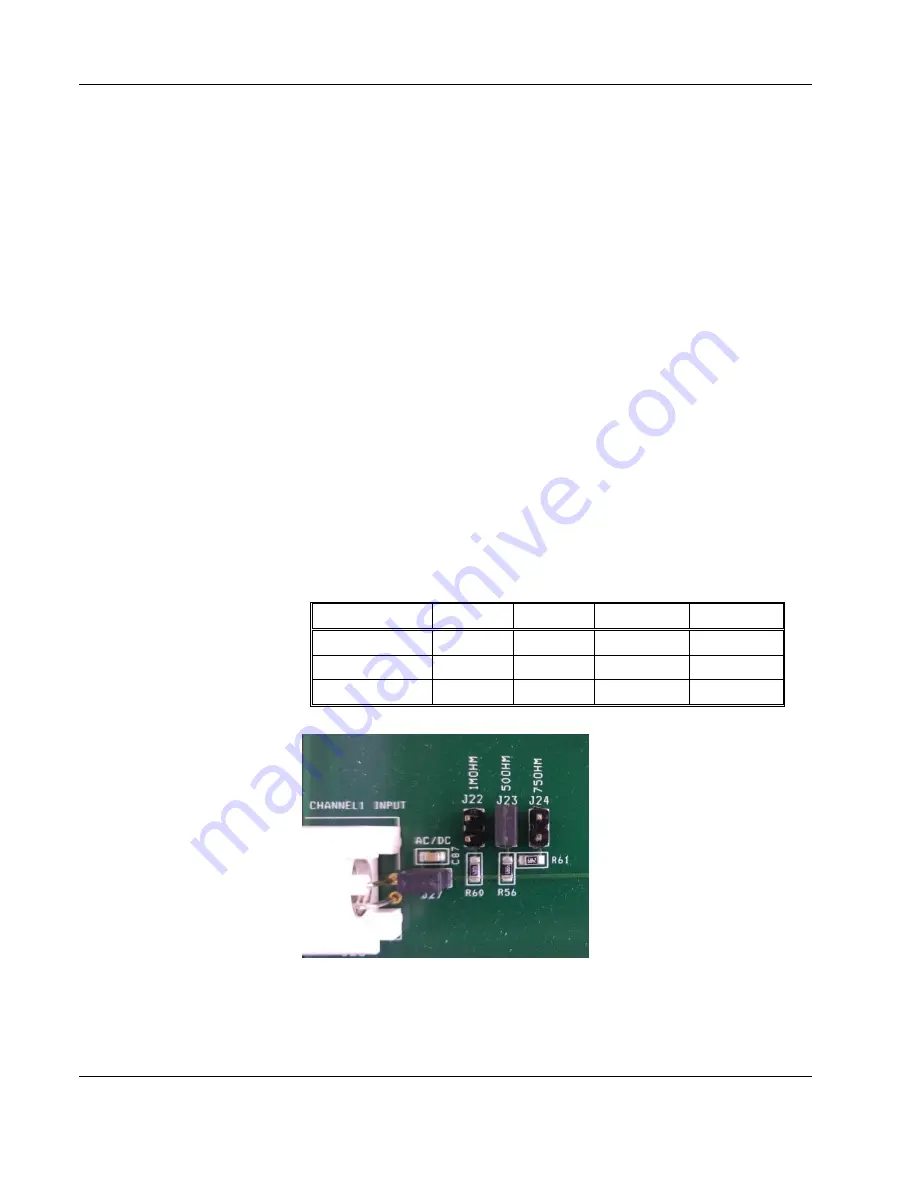
the jumper location for all of the inputs. Figure 2-1 shows an example
of the channel 1 input impedance jumpers. Place the jumpers as
required according to the following table:
Table
2-1, Input Impedance Jumpers
Impedance
CH1
CH2
Aux CH1
Aux CH2
50
Ω
J23
J5
J29
J14
75
Ω
J24
J11
J28
J13
1M
Ω
J22
J6
J30
J15
Figure
2-1, Field Modification of Channel 1 Input Impedance


