


38
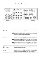
Remote control receiver
When using the remote control system please point the
SRC1
handset in the
direction of the receiver. It is essential to prevent potentially interfering light
(from fluorescent lamps and energy-saving bulbs) falling directly on the
receiver, as this may markedly reduce the effective range of the remote control
system. The line of sight between the
SRC1
and the remote control receiver in
the
PA 2500 R
must not be interrupted by any obstacles. Installing the
PA 2500 R
behind the glass doors of a cabinet will also adversely affect the
remote control system. The operating range of the
SRC1
remote control
handset with the internal infrared receiver of the
PA 2500 R
is about 4...5 m.
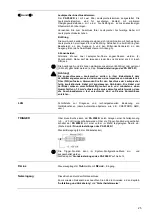
Screen
I
nformation relating to the machine’s status is displayed on the integral graphic
screen of the
PA 2500 R
, as is the menu navigation system. The screen
brightness can be adjusted to any of several levels (see chapter entitled
The
PA 2500 R
features two screen modes
Normal display
Detail display with VU meter - average value display with peak value
You can switch the VU meter on or off in configuration menu.
(see chapter entitled
‘Basic settings of the PA 2500 R’
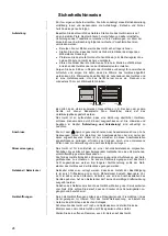
Normal display
Large-format display of the
most important information
Detail display
Display with additional
superimposed level indicator
(VU meter)
Screen divisions
The displays and symbols shown on the screen vary according to the source
and settings which are currently active. The screen is divided into the following
areas:
Display area (a) shows the source name.
Display area (b) shows the volume level currently set.
Area (c) shows symbols which indicate the current mode of operation.
(For details refer next page “Screen symbols and their meaning”)
Display area (d) with the level display (VU meter) is only superimposed if the
detail display is selected.
Level display
(VU meter)
The purpose of the VU meter is to display and monitor the modulation of the
PA 2500 R
. This display is a combination of delayed average display plus the
peak value measured over the last three seconds.
Содержание PA 2500 R
Страница 2: ...2...
Страница 15: ...15...
Страница 22: ...22...
Страница 33: ...33 English...
Страница 45: ...45...
Страница 52: ...52...
Страница 63: ...63 Anhang Appendix...
Страница 64: ...64 Anhang A Appendix A Anschluss Schema Wiring diagram...
Страница 69: ...69...