68/69 |
F-B90
The operator performs regular inspections of the dampers as per established regulations and standards at least once every 12
months. The inspection needs to be performed by an employee who has been specifically trained for this purpose by the
manufacturer. The current fire damper condition determined during the inspection needs to be entered into the “Operating Log” along
with the date of the inspection, the legible name, surname and signature of the employee who performed the inspection. The
Operating Log includes a copy of the employee’s authorization.
Any discrepancies discovered must be entered in the Operating Log along with a proposal for their correction. The Operating Log can
be found in
https://design.systemair.com
Before the first installation, inspection must be performed under the same conditions as those applicable to the above-mentioned 12-
month inspections.
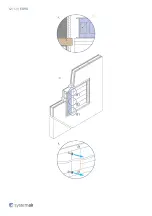
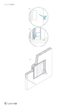
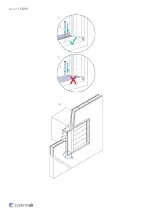
It is necessary to inspect the damper’s internal casing, the thermal fuse link, the sealing, the foaming substance, the damper blade’s
condition and its closure when it rests on a backstop in the closed position. There must be no other objects or dirt from the ventilation
duct inside the damper.
NEVER INSPECT THE DAMPERS WHEN THERE IS AIR FLOWING IN THE DUCT SYSTEM!
Recommended Inspection Steps According to the EN 15 650:
1. Damper identification
2. Date of inspection
3. Check the electrical connection of the activation mechanism (where applicable)
4. Check the damper for cleanliness and clean if necessary
5. Check the blade and sealing condition, corrections enter in log (if necessary)
6. Check for proper closure of the fire damper – for details, see the above sections
7. Check the operating functions of the damper: opening and closing using the control system, physical examination of the damper’s
behavior, correct if necessary and enter in log.
8. Check the operating functions of the end switches in the open and closed positions, correct if necessary and enter in log
9. Check whether the damper is fulfilling its role as part of the regulation system (where needed)
10. Check whether the damper remains in its standard operating position.
11. The damper is usually part of a system. In that case the whole system needs to be checked as described with respect to its
operation and requirements published by the builder of the system.
Supplement
Any deviations from the technical specifications contained in SystemairDESIGN and the terms should be discussed with the
manufacturer. We reserve the right to make any changes to the product without prior notice, provided that such changes do not affect
the quality of the product and the required parameters.
Содержание F-B90
Страница 1: ...F B90 Multiblade Fire damper ...
Страница 14: ...14 69 F B90 Dimensions Free area ...
Страница 15: ...15 69 F B90 Dimensions ...
Страница 16: ...16 69 F B90 Weights ...
Страница 17: ...17 69 F B90 ...
Страница 18: ...18 69 F B90 ...
Страница 23: ...23 69 F B90 Types 00 01 02 installed in the wall Max EI90S ...
Страница 24: ...24 69 F B90 ...
Страница 28: ...28 69 F B90 Types 11 22 installed in the wall Max EI90S EI120 ...
Страница 29: ...29 69 F B90 ...
Страница 32: ...32 69 F B90 Types 00 01 02 installed in the wall Max EI90S ...
Страница 33: ...33 69 F B90 ...
Страница 37: ...37 69 F B90 Types 11 22 installed in the wall Max EI90S EI120 ...
Страница 38: ...38 69 F B90 ...
Страница 41: ...41 69 F B90 Types 00 01 02 installed in the wall Max EI90S ...
Страница 44: ...44 69 F B90 Types 11 22 installed in the wall Max EI90S EI120 ...
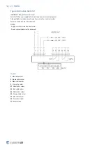
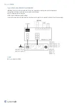
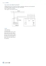
Страница 46: ...46 69 F B90 Electrical connections NOTE TS_P_A Type of activation Power Supply Power consumption Actuator type ...
Страница 47: ...47 69 F B90 ...
Страница 48: ...48 69 F B90 ...
Страница 49: ...49 69 F B90 ...
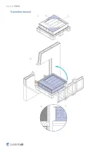
Страница 61: ...61 69 F B90 Operation manual ...
Страница 62: ...62 69 F B90 ...
Страница 63: ...63 69 F B90 ...
Страница 64: ...64 69 F B90 ...
Страница 66: ...66 69 F B90 ...
Страница 69: ...Systemair DESIGN 2020 10 07 HandBook_F_B90_en GB 1D2E1FF0 E010 11EA E8DD 8BBB7258CB9B ...

