


Annex
10—2
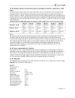
10.2
DVU
‐
internal
controller
for
the
cooling
compressor
system
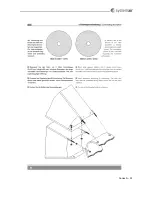
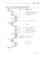
Two
LEDs
(light
diodes)
are
placed
on
the
DVU
‐
internal
controller
and
each
of
the
LEDs
can
be
on
or
flash
green,
red
or
orange.
During
normal
conditions
a
permanent
green
light
indicates
that
everything
is
normal,
orange
indicates
alternative
running
mode
while
red
indicates
alarm.
LED
Off
Green
flashing
Green
Orange
flashing
Orange
Red
flashing
Red
Upper
LED
Off
‐
signal
from
main
AHU
controller
..
On
‐
signal
from
main
AHU
controller
..
..
..
..
Lower
LED
..
..
Compressor
active
..
Hotgas
active
Alarm
..
Priorities
of
the
collars
are:
1.
Red
(highest
priority)
2.
Red
Flashing
3.
Orange
4.
Orange
Flashing
5.
Green
6.
Gren
Flashing
(Lowest
priority).
10.3
Background
illumination
of
the
display
Background
illumination
of
the
display
switches
on
automatically
when
the
potentiometer
is
turned
or
pressed.
The
illumination
switches
off
one
minute
after
the
last
activation
of
the
potentiometer.
By
alarm
the
illumination
flashes
until
the
alarm
is
acknowledged
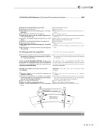
10.4
Potentiometer
on
the
internal
controller
for
the
cooling
compressor
system
The
potentiometer
is
the
only
tool
for
the
selection
of
menus
and
for
changing
parameters
in
the
DVU
‐
internal
controller.
The
potentiometer
is
at
the
right
side
of
the
display.
The
potentiometer
has
3
functions:
1.
Turn
clockwise
:
Go
to
the
next
menu
item
or
increase
parameter
value
2.
Turn
anticlockwise
:
Go
to
the
previous
menu
item
or
decrease
parameter
value
3.
Press
:
Select
menu,
start
change
of
parameter
or
acknowledge
and
store
new
value
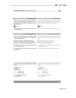
10.5
Selection
of
menu
Turn
the
knob
to
change
menu.
When
an
arrow
is
shown
to
the
right
at
the
bottom
of
the
display,
the
menu
has
a
submenu.
The
submenu
is
activated
by
pressing
the
knob
once.
If
the
knob
is
turned
in
the
submenu
you
will
scroll
between
the
items
in
the
submenu.
Leave
the
submenu
by
turning
the
potentiometer
clockwise
or
anticlockwise
until
the
"menu
up"
is
shown.
Press
to
leave
the
submenu.
10.6
Change
parameters
Turn
the
knob
until
the
required
parameter
is
shown
in
the
display.
Press
the
knob
and
turn
until
the
required
value
is
shown.
Press
the
button
once
more
to
acknowledge
and
store
the
value.
Flashing
parameter
value
in
the
display
indicates
that
changes
are
being
made
and
not
yet
acknowledged
and
stored.
Содержание Danvent DV
Страница 28: ...Bilag 8 8...
Страница 33: ...Annex 9 5...
Страница 34: ...Annex 9 6 A1 Size Quantity Length mm DV 60 4 1014 DV 80 4 1164 DV 100 4 1314 DV 120 4 1464 DV 150 4 1614 A1...
Страница 36: ...Annex 9 8 9 3 Assemble divided rotor for DV 60 DV 80 DV 100 DV 120 og DV 150...
Страница 37: ...Annex 9 9...
Страница 38: ...Annex 9 10...
Страница 39: ...Annex 9 11...
Страница 40: ...Annex 9 12...
Страница 41: ...Annex 9 13...
Страница 42: ...Annex 9 14...
Страница 43: ...Annex 9 15...
Страница 44: ...Annex 9 16...
Страница 45: ...Annex 9 17...
Страница 46: ...Annex 9 18...
Страница 47: ...Annex 9 19 9 4 Assemble divided rotor for DV 190 og DV 240...
Страница 48: ...Annex 9 20...
Страница 49: ...Annex 9 21...
Страница 50: ...Annex 9 22...
Страница 51: ...Annex 9 23...
Страница 52: ...Annex 9 24...
Страница 53: ...Annex 9 25...
Страница 54: ...Annex 9 26...
Страница 55: ...Annex 9 27...
Страница 56: ...Annex 9 28...
Страница 57: ...Annex 9 29...
Страница 58: ...Annex 9 30...
Страница 71: ...Annex 12 3...
Страница 75: ...Annex 12 7...
Страница 76: ...Annex 12 8 Systemair A S Ved Milep len 7 DK 8361 Hasselager Tel 0045 8738 7500 www systemair dk...


