10
Electrical connections cont'd
X6
1. 24 V
X6 SENSOR
Connection for CO sensor supply connection and measuring signal
connection
2. 4-20 mA
3. EARTH
X7
1. NC
X7 ALARM
Potential-free alarm contact connection option for controlling an
alarm siren or other auxiliary device.
2. COM
3. NO
8.3.1
Fan speed specification
The minimum fan speed can be set via a potentiometer in the range from 20 % to 40 %. The potentiometer is only ac-
cessible once the housing cover has been removed. The fan speed increases proportionately to the CO concentration
until the maximum speed at 50 ppm. If a fault is detected, the fans operate at maximum speed in order to remove any
raised CO concentrations in the air. The following table provides information about the control unit's speed specifica-
tions to the fans.
Table 6 Fan speed specification
CO concentration
Speed specification values
Comment
CO < 15 ppm Switch-off hysteresis 10
ppm
0 V
Fan standstill
CO = 15 ppm
2 V…4 V (min.)
Speed depending on set value
15 ppm < CO ≤ 50 ppm
Min.…10 V
Linear rise in the characteristic curve
analogue to the CO concentration
starting with the minimum through to
the maximum fan speed
50 ppm < CO
10 V
Maximum fan speed
Fault
10 V
Maximum fan speed
8.4
Protecting the motor
Note:
In fans equipped with an EC motor, there is no additional motor protection needed. The motor protection is
integrated in the electronics of the motor.
Important
Damage to motor due to overcurrent, overload or short circiut.
♦
Lead-out temperature monitors must be integrated in the control circuit in such a way that, if a fault
occurs, the motor cannot switch on again automatically after it has cooled down.
♦
Motor lines and temperature monitor lines should be laid separately on principle.
♦
Without thermal protection: Use a motor protection switch!
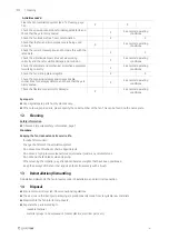
9
Commissioning
Warranty claims can only be made if commissioning work is carried out correctly and written evidence thereof is
provided.
Safety information
♦
Observe 2
Preconditions
♦
Installation and electrical connection have been
correctly performed.
♦
Before switching the fan on, check for externally
visible damage and ensure that the protective
equipment functions properly.
♦
Inlet and outlet are free.
♦
Cable glands are tight.
♦
Safety devices have been fitted.
| 005
Содержание 247027
Страница 4: ......
Страница 21: ... 005 ...


