9
CON11
N
blue
Neutral conductor
CON12
PE
green/yellow
GND-connection
2
0...10 V PWM
yellow
Controller input 0...10 V or PWM
4
Tacho
white
Speed output: Open Collector, 1 impulse per revolution,
electrically isolated, Isink_max = 10 mA
3
10 V
red
Voltage output 10 V, Imax. 10 mA, short-circuit-proof,
power supply for external devices.
1
GND
blue
GND-connection of the controller interface
8.3
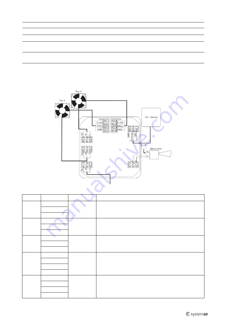
Wiring IV Smart EC-CO
The wiring diagram of the IV Smart EC-CO fan is not included in this document, but within this delivery.
Table 5 Electrical connections
Name
Occupancy
Designation
Description
X1
1. L
X1 SUPPLY
Supply connection to the control unit
2. N
3. PE
X2
1. L
X2 FAN1
Supply connection to fan 1. Voltage corresponds to the control unit's
supply voltage
2. N
3. PE
X3
1. L
X3 FAN2
Supply connection to fan 2. Voltage corresponds to the control unit's
supply voltage
2. N
3. PE
X4
1. 10 V
X4 FAN1
Control connection to fan 1. Speed specification and speed
feedback. If the fan has a 10 V output, it can be connected to
terminal X4.1.
2. 0-10 V
3. HALL
4. GND
X5
1. 10 V
X5 FAN2
Control connection to fan 2. Speed specification and speed
feedback. If the fan has a 10 V output, it can be connected to
terminal X5.1.
2. 0-10 V
3. HALL
4. GND
| 005
Содержание 247027
Страница 4: ......
Страница 21: ... 005 ...


