System Sensor BEAM200 Скачать руководство пользователя страница 7

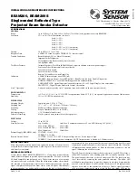
fIgURE 10. SwITCh LOCATIONS:

ALIGNMENT

SENSITIVITY

TEST

RESET

STYLE 7 ISOLATOR SHUNTS

(SHOWN DISABLED)

CODE SWITCH -   

TENS    ONES

C0263-00

fIgURE 11. ALIgNMENT ADjUSTMENT LOCATIONS:

ALIGNMENT MIRROR

ALIGNMENT GUNSIGHT

DIGITAL SIGNAL

STRENGTH

READOUT

HORIZONTAL

ADJUSTMENT

VERTICAL

ADJUSTMENT

OPTICS

LOCK-DOWN

SCREWS

ALIGNMENT

POSITION

INDICATOR

C0264-00

fIgURE 12. COARSE ALIgNMENT PROCEDURE:

EYE

REFLECTOR

C0265-00

fIgURE 13. hOUSINg SCREw LOCATIONS:

SCREW LOCATIONS

RESET SWITCH

C0266-00

ShORT CIRCUIT ISOLATION

The detector includes an on-board circuit isolator that allows for NFPA72 style 
7 operation. In cases where style 7 operation is not desired the isolator can be 
disabled using the two shunts on the circuit board. See Figure 10 for jumper 
locations. When the jumpers are present the isolator is disabled. This is the 
default state.

SENSITIvITy SELECTION

The  detector  has  six  sensitivity  selections.  Each  of  these  selections  is  only 
acceptable over a specific distance separation between the detector and the 
reflector per UL268. The chart below is used to determine which selections are 
acceptable for your installed distance. The sensitivity of the detector can be 
set only when the housing is removed and the detector is not in the fine ad-
justment step of the alignment mode, indicated by the illumination of the dual 
digital display. To set the sensitivity depress the sensitivity button one time. 
See Figure 10. Once the switch is pressed the digital display will illuminate 
and read the current sensitivity setting in percent obscuration. To change the 
sensitivity continue to depress the sensitivity switch until the desired setting 
is achieved. The digital display will turn off automatically if no further switch 
presses occur.

D400-74-00 

I56-2289-005R

Содержание BEAM200

Страница 1: ...1 communication every 5 sec LED flashing SLC 24 V Max Alarm LED on 8 5mA Max Max Trouble LED on 4 5mA Max Max Alignment 20mA Max External Supply BEAM200S only VOLTAGE 15 to 32 VDC CURRENT 0 5A Max Remote Output alarm VOLTAGE 15 to 32 VDC NOTE Output voltage same as device input voltage CURRENT 15mA maximum 6mA minimum NOTE Output current is limited by 2 2Kohm resistor I56 2289 005R 3825 Ohio Avenu...

Страница 2: ... The kit includes the hardware neces sary to mount either a single transmitter receiver unit or a single reflector To mount the transmitter receiver the surface mount kit BEAMSMK must also be used If the transmitter receiver and the reflector require additional alignment range two kits are required The kit is not compatible with the long range reflector kit BEAMLRK BEAMSMK The BEAMSMK allows Syste...

Страница 3: ...ures size and shape of the room and bays occupancy and uses of the area ceiling height ceiling shape surface and obstructions ventilation ambi ent environment burning characteristics of the combustible materials present and the configuration of the contents in the area to be protected Figure 3 Sloped ceiling shed type S 3 FT 0 9M MAX S 1 2 S MAX Tx Rx REFLECTOR C0256 00 Figure 4 Sloped ceiling pea...

Страница 4: ...detector will not be able to distinguish these reflections from those of the re flector and the protected space will be compromised Panes of glass will also absorb some of the light as it passes through it This absorption of light will reduce the acceptable installed distance between the detector and the reflector In cases where operation through panes of glass cannot be avoided some spe cific ins...

Страница 5: ...r alignment of the product If the detector and reflector are mounted per Mounting Loca tions and Mounting Instructions sections of this manual and the alignment procedures are executed properly false alarms and nuisance trouble signals will be minimized Pre Alignment Checklist Ensure that both the detector and reflector are mounted securely to stable surfaces Ensure that all wiring is correct Ensu...

Страница 6: ...ncrease the electronic gain 4 Once satisfied that it is not possible to achieve a higher reading on the display depress the alignment switch to complete the fine adjustment step The digital display readout will turn OFF and the yellow LED will remain ON NOTE It may not be possible to achieve a value near 90 on the display during the last adjustment iteration The final value of the display will not...

Страница 7: ...t the isolator is disabled This is the default state Sensitivity Selection The detector has six sensitivity selections Each of these selections is only acceptable over a specific distance separation between the detector and the reflector per UL268 The chart below is used to determine which selections are acceptable for your installed distance The sensitivity of the detector can be set only when th...

Страница 8: ...m of 1 minute 3 Place the blocking material over the reflector lining it up with the graduated marks that are 10 more than the detectors setting in obscuration The detector should enter alarm within 1 minute Figure 14 Reflector Test Card Procedure LINE UP EDGE OF TEST CARD WITH APPROPRIATE OBSCURATION LEVEL MOVE TEST CARD TO DESIRED AMOUNT OF OBSCURATION C0267 00 4 The detector can be reset with t...

Страница 9: ...h to work Maintenance NOTE Before cleaning the detector notify the proper authorities that the smoke detector system is undergoing maintenance and therefore the system will be temporarily out of service Disable the zone or system undergoing maintenance to prevent unwanted alarms 1 Carefully clean the outer housing lens face A damp soft cloth with a mild soap may be used Avoid products with solvent...

Страница 10: ...er Range Off 2 Quick Blinks Blink Blink Off Increase of Reflected Signal Inspect line of sight between detector and reflector for reflective objects in the pathway Trouble Beam Blockage Response Off 4 Quick Blinks Blink Blink Off Beam Blockage Remove blockage Faulty unit Initialization Power on Off Blink until complete Blink Blink Off Apply Power from discharged state Initialization alignment exit...

Страница 11: ...Scale 1 1 D400 74 00 11 I56 2289 005R Appendix II Detector Drilling Template 4 345 6 190 157 mm 110 mm ...

Страница 12: ...D400 74 00 12 I56 2289 005R ...

Страница 13: ...Appendix III Reflector Drilling Template Scale 1 1 5 512 140mm 8 465 215mm D400 74 00 13 I56 2289 005R ...

Страница 14: ...D400 74 00 14 I56 2289 005R ...

Страница 15: ...o not allow the exclusion or limitation of incidental or consequential damages so the above limitation or exclusion may not apply to you This Warranty gives you specific legal rights and you may also have other rights which vary from state to state Three Year Limited Warranty FCC Statement This device complies with part 15 of the FCC Rules Operation is subject to the following two conditions 1 Thi...

Отзывы: