SS-400-000
4
I56-3065-000R
NOTE:
This procedure should only be used in an emergency, and
it is not intended as a permanent substitute for ordering the cor-
rect length tubes.
Step 6. Field Wiring
Wiring Installation Guidelines
All wiring must be installed in compliance with the local codes
having jurisdiction. Proper wire gauges should be used. The con-
ductors used to connect smoke detectors to control panels and ac-
cessory devices should be color-coded to prevent wiring mistakes.
Improper connections can prevent a system from responding
properly in the event of a fire.
For signal wiring, (the wiring between interconnected detectors
or from detectors to auxiliary devices), it is recommended that
single-conductor wire be no smaller than 16 gauge (1.5 square
mm), and that two- or three-conductor wire be no smaller than
18 gauge (1.0 square mm). The last foot or so of conduit should
be flexible steel conduit (available in electrical supply houses)
which facilitates easier installation and puts less strain on the
conduit holes in the housing. Solid conduit connections may be
used if desired.
Smoke detectors and alarm system control panels have specifi-
cations for allowable loop resistance. Consult the control panel
manufacturer’s specifications for the total loop resistance allowed
for the particular model control panel being used before wiring
the detector loop.
Wiring Instructions
The 7251DH is designed for easy wiring. The housing provides a
terminal strip with clamping plates. Wiring connections are made
by stripping approximately
1
/
2
˝ of insulation from the end of the
wire, sliding this bare end under the plate, and tightening the
clamping plate screw.
Step 7. Install the Filters
Most duct installations are subject to dust accumulation. System
filters remove a large percentage of this contamination, but
cannot remove all of it. Dust inside the duct detector causes
problems. First, very fine particles of dust can enter the detector
sensing chamber and cause the unit to go into alarm. Second,
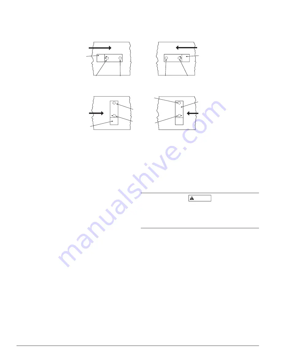
AIR FLOW
DIRECTION
DETECTOR
HOUSING
DOTS INDICATE POSITION OF
SAMPLING TUBE HOLES
AIR FLOW
DIRECTION
DETECTOR
HOUSING
INLET
TUBE
EXHAUST
TUBE
AIR FLOW
DIRECTION
EXHAUST
TUBE
INLET
TUBE
INLET
TUBE
EXHAUST
TUBE
DETECTOR
HOUSING
AIR FLOW
DIRECTION
EXHAUST
TUBE
INLET
TUBE
DETECTOR
HOUSING
A.
B.
C.
D.
HORIZONTAL MOUNTING OF HOUSING
VERTICAL MOUNTING OF HOUSING
Figure 5. Tube mounting configurations with varying air flow direction and orientation of detector housing.
Vertical as well as horizontal mounting is acceptable:
H0109-00
the accumulation of dust and dirt necessitates a more frequent
periodic cleaning schedule, which can result in substantial cost
and/or down time.
Disposable sampling tube filters can greatly reduce the nuisance
alarms caused by dust, and can also significantly extend the
maintenance interval. To install the sampling tube filters, simply
push the filter adapter into the exhaust tube, and then push the
filter onto the adapter tube on the left, as shown in Figure 6. Then
install the other filter over the end of the inlet sampling tube.
CAUTION
Filters require periodic cleaning or replacement, depending on the
amount of dust and dirt accumulated. Visually inspect the filters
at least quarterly; inspect them more often if the dust accumula-
tion warrants it. Replacement filters can be ordered from System
Sensor (exhaust tube/intake tube filter P/N F36-05-00).
The filters do not substantially affect smoke performance under
normal conditions. There is very little restriction of smoke entry
even when up to 90% of the filter is clogged. Visual inspection
is usually adequate to determine whether the filters should be
replaced because such a high percentage of contamination is re-
quired to affect performance.
However, if further testing is desired, a Dwyer Model 460 (or
equivalent) Differential Pressure Gauge may be used. Simply com-
pare the differential pressure readings with and without the filters
attached. There should be little or no difference. If the difference
exceeds 10%, replace the filters. In no case, however, should the
pressure differential be less than 0.01 inches of water or greater
than 1.2 inches of water.
Step 8. Perform Detector Check
8.1 Air Flow
1. To verify sufficient sampling of ducted air, use a manometer
to measure the differential pressure created from air flow
across the sampling tubes. The pressure should measure no
less than 0.01 inches of water and no greater than 1.20 inches
of water.
firealarmresources.com


