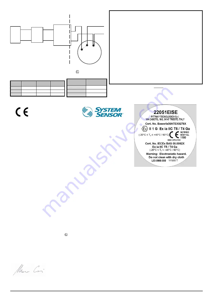
22051EISE System Diagram
SAFE AREA
(See Note 2)
HAZARDOUS AREA
Safe area apparatus, which is
unspecified except that it must not be
supplied from or contain under normal
or abnormal conditions a source of
potential with respect to earth in excess
of 253 Vrms or 253 VDC
Shunt Zener
Diode Safety
Barrier or
Isolation
Barrier (see
Note 1.)
To Next
Detector(s)
B501AP
2 & 4 linked in base
22051EISE
Smoke Detector
II1G Ex ia IIC T5, T4
Baseefa08ATEX0278X
Maximum Permissible Capacitance,
Inductance and Impedance Figures Across
Terminals 1 and 2 on a B501AP Base
Table 1
Table 2
Notes:
1. Any single channel shunt zener diode safety barrier or single channel of a
dual channel shunt zener diode safety barrier certified by Baseefa or any EEC
approved certification body to [EEx ia] IIC having the following or lower output
parameters:
Uz = 28V; Imax: out = 93.3 mA; Wmax: out = 0.66 W
In any safety barrier used, the output current must be limited by a resistor “R”,
such that Imax:out = Uz/R. Or any of the following isolation barriers may be
used:
P & F Smart Fire Detector Isolator Type KFDO-CS-Ex1.54-Y72221
One channel from: P & F Smart Fire Detector Isolator Type KFDO-CS-Ex2.54-
Y72222 (BAS00ATEX7087X)
2. The capacitance and either inductance or inductance/resistance (L/R) ratio of
the cable connected to the hazardous area terminals of barrier must not exceed
the values shown in Table 1.
3. The installation must comply with the appropriate national installation
requirements, e.g. in the U.K. to BSEN60079-14: 1997.
4. The electrical circuit in the hazardous area must be capable of withstanding
an A.C. test voltage of 500 VRMS to earth or frame of the equipment, for a
period of one minute without breakdown. This note does not apply when using
an isolation barrier.
R12-172-00, REV G
CAUTION
Please refer to control panel installation instructions for specific barrier/control panel
compatibility information.
Control
Panel
IST200
Translator
Module
2 (+)
1 (-)
4 (+)
0832
0832-CPD-0199
EC DECLARATION OF CONFORMITY
Date of issue:
07 November 2012
Manufacturer:
Pittway Tecnologica Srl
Via Caboto 19/3
34147 TRIESTE
Italy
Product: 22051EIS
E
Bases:
B501, B501AP
Description:
Intrinsically Safe Analogue addressable photoelectric smoke detector
We hereby declare that the product identified above meets the requirements of the following EC
Directives and therefore qualify for free movement within markets comprising the European Union
(EU) and the European Economic Area (EEA):
EMC Directive 2004/108/EC
EU Construction Products Directive, 89/106/EEC
Conforms to:
EN54 - 7: 2000 + A1: 2002 + A2:2006
Notified Body:
BRE - LPCB
Notified Body Number:
0832
EC Certificate Number
0832-CPD-0199
ATEX 94/9/EEC
Conforms to:
EN60079-0: 2006, EN60079-11: 2007
EN60079-26:2007
Notified Body:
Baseefa
Notified Body Number:
1180
Certificate Number
Baseefa08ATEX0278X
Rating
II 1G Ex ia IIC T5 / T4 Ga (-20°C ≤Ta≤ 40°C/60°C)
For and on behalf of
Pittway Tecnologica S.r.l.
Marco Corti
Plant Manager
Pittway Tecnologica S.r.l.
a socio unico
Via Caboto 19/3
34147 TRIESTE (Italy)
Tel: +39-040-9490111
Fax: +39-040-382137
N. IVA IT 00744320326
Reg. Impr. TS n. 10331 Trib. TS
R.E.A. N. 97799
Cap.Soc. € 1.368.619,00 int. vers.
P.IVA e Cod. Fisc. 00744320326
Group Capacitance
µF
Inductance
mH
L/R Ratio
µH/Ohm
IIC
0.083 4.2 55
IIB
0.65 12.6 210
IIA
2.15 33.6 444
B501AP Pins Connection
1
-V IN, -V OUT
2
+V IN
4
+V OUT


