background image

Manuale v300/v600

Doc #5002 (Italian)  07/2004


5

Avvertenze di sicurezza e di pericolo!

Avvertenze di carattere generale

Il sistema può essere usato solo da persone specialmente addestrate al 

funzionamento e all’uso in condizioni di sicurezza.

Tenere il sistema fuori della portata dei bambini.
Non camminare o passare con veicoli a ruota su cavi e funi.
Non tendere eccessivamente cavi e funi per evitare un’usura precoce.
Non far cadere a terra alcun componente del sistema. L’urto può causare danni 

permanenti.

Non pulire i componenti del sistema con abrasivi o solventi.
Non sterilizzare in autoclave i componenti del sistema.
Non inserire oggetti nelle aperture dei componenti del sistema.
Non dirigere la luce del modulo d’illuminazione verso gli occhi di altre persone 

e non fissare lo sguardo direttamente nel modulo quando è acceso.

Non usare il sistema come una luce per attraversare un ambiente buio.

Pericoli elettrici

Non immergere mai alcuna componente del sistema in acqua o altri liquidi.
Usare solo prese di corrente approvate e collegate con la terra.
Evitare il contatto di oggetti metallici o di qualsiasi parte del corpo con le 

connessioni elettriche.

Non usare mai alcun’altra fonte di alimentazione con questo sistema. I danni 

risultanti dal ricorso ad una fonte di alimentazione diversa dal modulo fornito, 
rendono nulla la garanzia.

Con il sistema usare sempre il modulo di alimentazione fornito. Il sistema 

è concepito per funzionare con questo modulo allo scopo di assicurare 
un’interfaccia di sicurezza tra l’utente e la fonte di alimentazione.

Staccare il modulo di fornitura della corrente quando si connettono o 

disconnettono cavi ai componenti del sistema.

Pericoli d’incendio

Non usare l’unità in un’atmosfera infiammabile od esplosiva.
Non bloccare alcuna apertura del sistema, per evitare un surriscaldamento del 

modulo d’illuminazione.

Evitare il funzionamento dell’unità in ambienti polverosi.


Содержание v300TM

Страница 1: ...ation v300 v600 Benutzerhandbuch German v300 v600 Visualisierungssystem Manuale del Proprietario Italian v300 v600 Sistema di Visualizzazione Manual del Propierario Spanish Sistema de Visualización Serie v300 v600 Doc 5002 Revision 3 July 2004 v300TM v600TM Visualization System International Owner s Manual ...

Страница 2: ...Revision 3 July 2004 English v300TM v600TM Visualization System Owner s Manual ...

Страница 3: ...57 7051 Email techsupport syrisscientific com Web www syrisscientific com Service Center Hours Monday Friday 8 00AM 5 00PM US Eastern Time Authorized European Representative CEpartner4U BV Esdoornlaan 13 3951DB Maarn The Netherlands Phone 31 0 343 442 524 Cell 31 0 6 516 536 26 Fax 31 0 343 442 162 Email office cepartner4u nl Contact Theo Nusselder Harry Teirlinck ...

Страница 4: ...ts by following the care and use instruction provided in this manual Please do not hesitate to call our service group at 800 714 1374 or 207 657 7050 if we can be of any assistance in the use of your new system Syris Scientific LLC Table of Contents Legend 4 Safety Warnings and Hazards 5 Product Description 6 Product Setup 8 Product Operation 10 Illuminator Replacement 11 Handling Cleaning and Stor...

Страница 5: ...300 and v600 Visualization Systems Symbol Title Definition Attention Consult accompanying documents Dangerous Voltage Warning dangerous voltage present CE Conformity Mark Product conforms to the requirements of applicable EU directives On Off Direct Current DC Alternating Current AC Volts Direct Current Amperes ...

Страница 6: ...le it is on Do not use the system as a light to navigate your environment Electrical Hazards Never immerse any component of the system in water or other liquids Use only an approved grounded outlet Do not allow metal objects or body parts to touch electrical connections Do not use any other power supply with this system Damage resulting from use of a power supply other than the Power Supply Module...

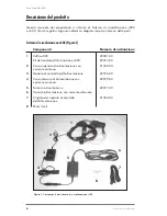
Страница 7: ...ystem are presented here v300 Visualization System Figure 1 Components Part Number 1 v300 Headgear Z2001 00 v300 Illuminator Z2074 00 2 Upper DC Power Cable Z1762 00 3 Power Control Module Z2076 00 4 Lower DC Power Cable Z2079 00 5 Power Supply Z2077 00 6 AC Power Cable 7 Power Control Module Belt Z1763 00 8 Lens Wipes Figure 1 v300 Visualization System Components 1 2 3 4 5 6 7 8 ...

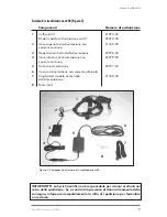
Страница 8: ...rol Module Z2076 00 4 Lower DC Power Cable Z2079 00 5 Power Supply Z2077 00 6 AC Power Cable 7 Power Control Module Belt Z1763 00 8 Lens Wipes IMPORTANT Syris Scientific is not responsible for any damage that may have resulted from shipping Should you find any damage to your system please call the shipping company immediately to fill out a claim Figure 2 v600 Visualization System Components 1 2 3 4 5...

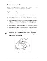
Страница 9: ...ning it counter clockwise 3 Position the Headgear on your head ensuring that the front of the headband sits comfortably above your eyebrows If the Headgear sits too high or two low on your head repeat step one 4 Tighten the headband by pushing the knob at the back of the headband and turning it clockwise 5 Adjust the position of the Visi Shield by turning the knobs on either side of the Headgear W...

Страница 10: ...N connector of the Power Supply 5 Plug the IEC connector of the AC Power Cord into the IEC port on the Power Supply 6 Plug the AC plug of the AC Power Cord into an approved outlet After completing the wiring setup procedure turn the switch of the Power Control Module to on You should immediately hear the fan of the Illuminator Module turn on To prevent shock to the Illuminator Module the system is...

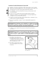
Страница 11: ...ce viewing mode use the following simple procedure 1 While wearing the Headgear locate the Illuminator Module with your free hand 2 Slide your hand down the Illuminator Module until you locate the adjustment peg located at the front of the barrel 3 Gently grasp the adjustment peg and rotate it as shown in Figure 4 4 As worn on the head the surface parallel polarized mode will be seen when the adju...

Страница 12: ...unction set is a display of the Illuminator Module s 1 in Fig 1 condition Three colored LED s are installed to be visible through the air outlet vents on the rear of the illuminator Green Will remain visible for the first 75 of its life expectancy Yellow Will indicate 5 24 of life expectancy remains It is suggested to order replacement at this point Red Will indicate less than 5 of life expectancy ...

Страница 13: ...nator Module to cool at least ten minutes before proceeding 3 Loosen the plastic wing nuts on either side of the old Illuminator Module approximately one turn and remove it from the Headgear frame 4 Install the new Illuminator Module on the Headgear frame and tighten the plastic wing nuts 5 Connect the Upper DC Power Cable to the Illuminator Module and plug AC Power Input Cable into a wall outlet ...

Страница 14: ...and remove the new Illuminator Module from its plastic wrapper IMPORTANT Do not allow the Illuminator Module bulb or reflector to come in contact with exposed skin or other foreign material This may cause premature failure of the Illuminator Module 6 Install the new Illuminator Module in the optics tube by screwing it clockwise IMPORTANT Do not force the new Illuminator Module into the optics tube ...

Страница 15: ...oduct warranty Cleaning Clean the system after every use that may have caused contamination Clean the entire product with approved disinfectant towelettes or towelettes containing isopropyl alcohol Never clean any component of the system with hard or abrasive objects After cleaning the system it is recommended that the Visi Shield and magnifying lenses be wiped with optical cloth or equivalent non...

Страница 16: ...u would like to order any of the following parts or accessories for your v300 or v600 Visualization System Order Code Description Z1924 00 v600 Visualization System Z2001 00 v300 Visualization System Z2073 00 v600 Illuminator Module Kit Z2074 00 v300 Illuminator Module Kit Z2075 00 Visi Shield with 3 Diopter 1 75 X mag Lens Z2076 00 Power Control Module Z2077 00 v300 v600 Power Supply Z2079 00 Low...

Страница 17: ...ed by Syris Scientific in repairing or replacing the defective parts The external housing and cosmetic parts shall be free of defects at the time of shipment and therefore shall not be covered under these limited warranty terms 4 Upon request from Syris Scientific the Consumer must provide information to reasonably prove the date of purchase 5 The Consumer shall bear the cost of shipping and any dut...

Страница 18: ...mer will be invoiced for all shipping charges 10 Any implied warranty of the merchantability or fitness for a particular purpose or use shall be limited to the duration of the foregoing written warranty Otherwise the foregoing warranty is the Purchaser s sole and exclusive remedy and in lieu of all other warranties expressed or implied Syris Scientific shall not be liable of incidental or consequent...

Страница 19: ...18 www syrisscientific com Syris Scientific LLC ...

Страница 20: ...turn it by mail to Syris Scientific Please write clearly Name ________________________________________________________________ Address _______________________________________________________________ ____________________________________________________________________ Phone Area Code ____________________________________________________ Fax Area Code __________________________________________________...

Страница 21: ......

Страница 22: ...Revisie 3 juli 2004 Dutch v300TM v600TM Visualisatiesysteem Gebruikershandleiding ...

Страница 23: ...Email techsupport syrisscientific com Website www syrisscientific com Kantooruren Servicecentrum maandag t m vrijdag 8 00 17 00 u Eastern Standard Time Europees Gevolmachtigde CEpartner4U BV Esdoornlaan 13 3951DB Maarn The Netherlands Telefoon 31 0 343 442 524 Cell 31 0 6 516 536 26 Fax 31 0 343 442 162 Email office cepartner4u nl Contact Theo Nusselder Harry Teirlinck ...

Страница 24: ...rstrekte verzorgings en gebruiksinstructies te volgen Als wij u bij het gebruik van uw nieuwe systeem van dienst kunnen zijn aarzel dan a u b niet onze servicegroep te bellen op telefoonnummer 207 657 7050 Syris Scientific LLC Inhoudsopgave Verklaring van symbolen 4 Veiligheidswaarschuwingen en gevaren 5 Productbeschrijving 6 Productinstelling 8 Werking van het product 10 Vervanging van de Illumina...

Страница 25: ...ualisatiesystemen aangetroffen Symbool Naam Verklaring Attentie Raadpleeg de begeleidende documenten Gevaarlijk voltage Waarschuwing er is gevaar lijke elektrische spanning aanwezig CE Conformiteitsmerk Het product voldoet aan de eisen van de toepasselijke EU richtlijnen Aan Uit Gelijkstroom DC Wisselstroom AC Gelijkstroomvoltage Ampère ...

Страница 26: ... terwijl deze aanstaat Het systeem moet niet worden gebruikt als verlichting om u de weg in uw omgeving te wijzen Elektrische gevaren Dompel geen enkel onderdeel van het systeem ooit in water of andere vloeistoffen onder Gebruik uitsluitend een goedgekeurd en geaard stopcontact Laat geen metalen voorwerpen of lichaamsdelen de elektrische aansluitingen aanraken Gebruik nooit enige andere stroomtoev...

Страница 27: ...steem vermeld v300 Visualisatiesysteem Figuur 1 Onderdelen Bestelcode 1 v300 hoofdtoestel Z2001 00 v300 Illuminator modulekit Z2074 00 2 Bovenste gelijkstroomsnoer Z1762 00 3 Stroomregelmodule Z2076 00 4 Onderste gelijkstroomsnoer Z2079 00 5 Stroomtoevoer Z2077 00 6 Wisselstroomsnoer 7 Stroomregelmoduleriem Z1763 00 8 Lensdoekjes Figuur 1 Onderdelen van het v300 Visualisatiesysteem 1 2 3 4 5 6 7 8...

Страница 28: ...regelmodule Z2076 00 4 Onderste gelijkstroomsnoer Z2079 00 5 Stroomtoevoer Z2077 00 6 Wisselstroomsnoer 7 Stroomregelmoduleriem Z1763 00 8 Lensdoekjes BELANGRIJK SyrisScientificisnietverantwoordelijkvoortijdensdeverzending opgelopen schade Als u beschadiging op uw systeem waarneemt belt u de expediteur onmiddellijk om een claim in te dienen Figuur 2 Onderdelen van het v600 Visualisatiesysteem 1 2 3...

Страница 29: ...draaien 3 Zet het hoofdtoestel op uw hoofd en verzeker dat de voorkant van de hoofdband comfortabel boven uw wenkbrauwen zit Herhaal stap 1 als het hoofdtoestel te hoog of te laag op uw hoofd zit 4 Haal de hoofdband aan door op de knop aan de achterkant van de hoofdband te drukken en hem rechtsom te draaien 5 Stel de positie van het Visi Shield bij door aan de knop op één of allebei kanten van het...

Страница 30: ... de IEC connector van het wisselstroomsnoer in de IEC poort van de stroomtoevoer 6 Steek de wisselstroomstekker van het wisselstroomsnoer in een goedgekeurd stopcontact Nadat de procedure voor de bedradingsopstelling voltooid is zet u de schakelaar van de stroomregelmodule op Aan U moet de ventilator van de Illuminator module onmiddellijk horen aankomen Om elektrische schok op de Illuminator modul...

Страница 31: ...or bovenhuidse of onderhuidse oppervlakken moet de volgende eenvoudige procedure worden gebruikt 1 Draag het hoofdtoestel en voel langs de Illuminator module met uw vrije hand 2 Beweeg uw hand langs de Illuminator module totdat u de bijstelknop aan de voorkant van de ombouw hebt gevonden 3 Pak de afstelknop voorzichtig beet en draai hem zoals afgebeeld in Figuur 4 4 Bij het op het hoofd dragen wor...

Страница 32: ...nditie van de Illuminator module 1 in figuur 1 Er zijn drie gekleurde LED s geïnstalleerd en zijn zichtbaar door de luchtuitlaten aan de achterkant van de Illuminator Groen blijft de eerste 75 van zijn verwachte levensduur zichtbaar Geel geeft aan dat er 5 24 van de verwachte levensduur overblijft De vervanging bestellen wordt nu aanbevolen Rood geeft aan dat er minder dan 5 verwachte levensduur ov...

Страница 33: ...en minuten afkoelen alvorens verder te gaan 3 Draai de plastic vleugelmoeren aan beide kanten van de oude Illuminator module ongeveer één slag om en verwijder de module uit het frame van het hoofdtoestel 4 Installeer de nieuwe Illuminator module in het hoofdtoestel en draai de plastic vleugelmoeren vast 5 Sluit het bovenste gelijkstroomsnoer op de Illuminator module aan en steek de stekker van de ...

Страница 34: ...euwe Illuminator module met de handschoen aan uit de plastic wikkel BELANGRIJK Laat de lamp of reflector van de Illuminator module niet in contact komen met de blootliggende huid of met andere vreemde voorwerpen Dit kan voortijdig weigeren van de Illuminator module veroorzaken 6 Installeer de nieuwe Illuminator module in de opticabuis door hem er rechtsom in te draaien BELANGRIJK De nieuwe Illumina...

Страница 35: ...uik waarbij het systeem verontreinigd kan zijn geraakt moet het worden schoongemaakt Propere het volledig product met goedgekeurd ontsmettingsmiddel towelettes of towelettes bevatten isopropyl van alcohol Geen onderdelen van het systeem moeten ooit met harde voorwerpen of schurende middelen worden gereinigd Het verdient aanbeveling dat het Visi Shield en de vergrootlenzen na de reiniging worden af...

Страница 36: ...050 als u de volgende onderdelen of accessoires wilt bestellen voor uw v300 of v600 Visualisatiesysteem Bestelcodede Beschrijving Z1924 00 v600 Visualisatiesysteem Z2001 00 v300 Visualisatiesysteem Z2073 00 v600 Illuminator modulekit Z2074 00 v300 Illuminator modulekit Z2075 00 Visi Shield met 3 diopter 1 75 X vergr lens Z2076 00 Stroomregelmodule Z2077 00 v300 v600 Stroomtoevoer Z2079 00 Onderste...

Страница 37: ... defecte onderdelen De buitenombouw en cosmetische onderdelen zullen ten tijde van verzending geen defecten vertonen en vallen daarom niet onder deze beperkte garantievoorwaarden 4 Op verzoek van Syris Scientific moet de consument informatie verschaffen om de aankoopdatum op aanvaardbare wijze te kunnen waarmaken 5 De consument moet de kosten van verzending en alle in of uitvoerrechten voor Syris S...

Страница 38: ...rneerd verzendkosten onder rembours Als het product na het verstrijken van de beperkte garantieperiode aan Syris Scientific wordt geretourneerd zal het normale servicebeleid van Syris Scientific van toepassing zijn en zullen alle verzendkosten aan de consument in rekening worden gebracht 10 Alle geïmpliceerde garanties van verkoopbaarheid of geschiktheid voor een bepaald doel of gebruik zullen beper...

Страница 39: ...hting of aansprakelijkheid zoals deze uitdrukkelijk in deze beperkte garantie worden verstrekt te boven gaat Aan de consument zullen alle niet onder deze garantie gedekte kosten voor onderdelen en arbeidskosten in rekening worden gebracht 13 De garantie s voor de door Syris Scientific geleverde accessoires en hulpstukken wordt worden specifiek op hun bijbehorende garantiekaarten en verpakkingen gede...

Страница 40: ...art in en stuur hem per post naar Syris Scientific Duidelijk schrijven a u b Naam ________________________________________________________________ Adres Woonplaats _________________________________________________________ ____________________________________________________________________ Telefoon kengetal __________________________________________________ Fax kengetal ____________________________...

Страница 41: ......

Страница 42: ...Système de visualisation v300TM v600TM Révision 3 Juillet 2004 French Manuel d utilisation ...

Страница 43: ...rt syrisscientific com Web www syrisscientific com Heures d ouverture du service après vente Lundi Vendredi 8 00 h 17 00 h Fuseau horaire de la Côte Est des États Unis Représentant européen autorisé CEpartner4U BV Esdoornlaan 13 3951DB Maarn The Netherlands Tél 31 0 343 442 524 Cell 31 0 6 516 536 26 Fax 31 0 343 442 162 Email office cepartner4u nl Contact Theo Nusselder Harry Teirlinck ...

Страница 44: ...instructions d utilisation et d entretien fournies dans ce manuel N hésitez pas à appeler notre groupe de service après vente au 207 657 7050 pour toute assistance concernant l usage de votre nouveau système Syris Scientific LLC Table des matières Légende 4 Avertissements de sécurité et risques 5 Description du produit 6 Installation du produit 8 Fonctionnement du produit 10 Remplacement de l illum...

Страница 45: ...300 et v600 Symbole Titre Définition Attention Consulter les documents d accompagnement Tension dangereuse Avertissement présence de tension dangereuse Marque de conformité CE Produit conforme aux exigenc es des directives applicables de l Union Européenne Marche Arrêt Courant continu CC Courant alternatif CA Volts courant continu Ampères ...

Страница 46: ...our naviguer dans votre environnement Risques électriques Ne jamais immerger d élément du système dans de l eau ou dans tout autre liquide Utiliser uniquement une prise électrique agréée mise à la terre Ne laisser aucun objet métallique ou partie corporelle toucher les connexions électriques N utiliser aucune autre source d alimentation avec ce système Tout endommagement découlant de l usage d une...

Страница 47: ...alisation v300 Figure 1 Éléments Code de commande 1 Casque v300 Z2001 00 Kit Module illuminateur v300 Z2074 00 2 Câble d alimentation CC supérieur Z1762 00 3 Module de commande de puissance Z2076 00 4 Câble d alimentation CC inférieur Z2079 00 5 Source d alimentation Z2077 00 6 Câble d alimentation CA 7 Ceinture Module de commande Z1763 00 de puissance 8 Essuie lentilles Figure 1 Éléments du systè...

Страница 48: ...tion CC inférieur Z2079 00 5 Source d alimentation Z2077 00 6 Câble d alimentation CA 7 Ceinture Module de commande Z1763 00 de puissance 8 Essuie lentilles IMPORTANT Syris Scientific n est responsable d aucun endommagement ayant pu survenir au cours de l expédition En cas d un tel endommagement de votre système veuillez vous adresser directement à la compagnie de transport pour faire une demande d...

Страница 49: ...ire des aiguilles d une montre 3 Placer le casque sur la tête en s assurant que l avant du serre tête repose confortablement au dessus des sourcils Si le casque repose trop haut ou trop bas sur la tête répéter l étape un 4 Serrer le serre tête en appuyant sur le bouton situé à l arrière de celui ci et en le faisant tourner dans le sens des aiguilles d une montre 5 Régler la position du Visi Shield...

Страница 50: ...a prise CEI du cordon d alimentation secteur sur le port CEI situé sur la source d alimentation 6 Brancher la prise de courant alternatif du cordon d alimentation secteur sur une prise de courant agréée Après avoir terminé la procédure de configuration du câblage mettre le commutateur du Module de commande de puissance sur Marche Vous devriez immédiatement entendre la mise en marche du ventilateur ...

Страница 51: ...le procédure suivante 1 Tout en portant le casque repérer le Module illuminateur à l aide de votre main libre 2 Faire glisser la main vers le bas du Module illuminateur jusqu à ce que vous trouviez la cheville de réglage située à l avant du barillet 3 Saisir doucement la cheville de réglage et la faire tourner comme indiqué à la Figure 4 Réglage de la polarisation 4 En position de port sur la tête...

Страница 52: ...Illuminateur 1 à la Fig 1 Trois DEL de couleur sont installées de manière à être visibles à travers les évents de sortie d air de l illuminateur Verte Demeure visible pendant les premiers 75 de sa durée de vie Jaune Indique une durée de vie restante de 5 à 24 Il es conseillé de procéder à un remplacement à ce point Rouge Indique une durée de vie restante de moins de 5 L ampoule alterne entre un ét...

Страница 53: ...t au moins dix minutes avant de poursuivre 3 Dévisser les écrous à oreilles en plastique situés d un côté ou de l autre de l ancien Module illuminateur d environ un tour et le sortir du cadre du casque 4 Installer le nouveau Module illuminateur sur le cadre du casque et serrer les écrous à oreilles en plastique 5 Raccorder le câble supérieur d alimentation en courant continu au Module illuminateur...

Страница 54: ...ain gantée sortir le nouveau Module illuminateur de son emballage plastique IMPORTANT Ne pas laisser l ampoule ni le réflecteur du Module illuminateur entrer en contact direct avec de la peau ou toute autre matière étrangère Ceci pourrait entraîner une défaillance prématurée du Module illuminateur 6 Installer le nouveau Module illuminateur dans le tube optique en le vissant dans le sens des aiguill...

Страница 55: ...limitée du produit Nettoyage Nettoyer le système après chaque usage susceptible d avoir entraîné une contamination Nettoyer le produit entier avec towelettes de désinfectant approuvé ou towelettes contenir l alcool d isopropyle Ne jamais nettoyer d élément du système à l aide d objets durs ou abrasifs Après avoir nettoyé le système il est conseillé d essuyer le Visi Shield et les lentilles de gros...

Страница 56: ...pour votre Système de visualisation v300 ou v600 Code de commande Description Z1924 00 Système de visualisation v600 Z2001 00 Système de visualisation v300 Z2073 00 Kit Module illuminateur v600 Z2074 00 Kit Module illuminateur v300 Z2075 00 Visi Shield avec lentille de 3 dioptries gross 1 75 X Z2076 00 Mode de commande de puissance Z2077 00 Source d alimentation v300 v600 Z2079 00 Câble d alimenta...

Страница 57: ...ueuses Le boîtier extérieur et les pièces cosmétiques doivent être libres de tout défaut au moment de l expédition et par conséquent ne sont pas couverts par les modalités de cette garantie limitée 4 Sur demande de Syris Scientific le consommateur doit fournir des informations prouvant de manière raisonnable la date d achat 5 Le Consommateur est responsable des frais d expédition et de toutes taxes...

Страница 58: ...oyé en port dû Si le Produit est renvoyé à Syris Scientific après l expiration de la période de garantie les conditions normales de service après vente de Syris Scientific s appliquent et le Consommateur recevra une facture pour tous les frais d expédition 10 Toute garantie implicite de qualité marchande ou de convenance à un but ou à un usage particulier est limitée à la durée de la garantie écrite...

Страница 59: ...obligation ou responsabilité au delà de ce qui est expressément stipulé dans cette garantie limitée Le consommateur se verra facturer tous les frais de pièces ou de main d œuvre non couverts par cette garantie limitée 13 Les garanties pour les accessoires et les fixations fournis par Syris Scientific sont spécialement définies sur leurs propres cartes de garantie et emballages ...

Страница 60: ...plir cette carte et la renvoyer par courrier à Syris Scientific Veuillez écrire lisiblement Nom _________________________________________________________________ Adresse _______________________________________________________________ ____________________________________________________________________ Tél Indicatif _______________________________________________________ Fax Indicatif ______________...

Страница 61: ......

Страница 62: ...Revision 3 Juli 2004 German Visualisierungssystem v300TM v600TM Benutzerhandbuch ...

Страница 63: ...port syrisscientific com Internet www syrisscientific com Öffnungszeiten des Kundendienstzentrums Montag Freitag 8 00 Uhr 17 00 Uhr US Ostküstenzeit MEZ 6 Bevollmächtigter in der Europäischen Union CEpartner4U BV Esdoornlaan 13 3951DB Maarn The Netherlands Telefon 31 0 343 442 524 Cell 31 0 6 516 536 26 Fax 31 0 343 442 162 Email office cepartner4u nl Contact Theo Nusselder Harry Terilinck ...

Страница 64: ...dbuch wird Ihnen dieses Produkt viele Jahre lang gute Dienste bei Ihren Eingriffen leisten Unsere Servicegruppe steht Ihnen unter der Rufnummer 1 207 657 7050 jederzeit zur Unterstützung mit Ihrem neuen System zur Verfügung Syris Scientific LLC Inhaltsverzeichnis Zeichenerklärung 4 Sicherheitswarnhinweise und Gefahren 5 Beschreibung des Produkts 6 Vorbereitung 8 Betrieb 10 Austausch des Illuminator...

Страница 65: ...folgenden Symbolen gekennzeichnet Symbol Name Beschreibung Achtung Auf die Begleitliteratur Bezug nehmen Gefährliche Spannung Warnung es liegt eine gefährliche Spannung an CE Konformitätszeichen Das Produkt erfüllt die Anforderungen der jeweils zutreffenden EU Direktiven Ein Aus Gleichstrom DC Wechselstrom AC Volt Gleichstrom Ampere ...

Страница 66: ... Verwenden Sie das System nicht als Licht zum Beleuchten Ihrer Umgebung Elektrische Gefahren Tauchen Sie Komponenten des Systems niemals in Wasser oder andere Flüssigkeiten ein Benutzen Sie nur zugelassene geerdete Stromsteckdosen Achten Sie darauf dass Metallobjekte oder Körperteile nicht mit elektrischen Anschlüssen in Berührung kommen Benutzen Sie kein anderes Netzteil mit diesem System Schäden...

Страница 67: ... Systeme v300 Visualisierungssystem Abb 1 Komponenten Best Nr 1 v300 Kopfteil Z2001 00 v300 Illuminatormodul Kit Z2074 00 2 Oberes Gleichstromausgangskabel Z1762 00 3 Stromreglermodul Z2076 00 4 Unteres Gleichstromausgangskabel Z2079 00 5 Netzteil Z2077 00 6 Wechselstromeingangskabel 7 Stromreglermodul Gürtel Z1763 00 8 Linsenreinigungstücher Abb 1 Komponenten des v300 Visualisierungssystems 1 2 3...

Страница 68: ...6 00 4 Unteres Gleichstromausgangskabel Z2079 00 5 Netzteil Z2077 00 6 Wechselstromeingangskabel 7 Stromreglermodul Gürtel Z1763 00 8 Linsenreinigungstücher WICHTIG Syris Scientific LLC ist nicht verantwortlich für Versandschäden Falls Sie Beschädigungen an Ihrem System feststellen sollten wenden Sie sich bitte sofort an den Spediteur um Schadensersatz zu beantragen Abb 2 Komponenten des v600 Visua...

Страница 69: ...egen den Uhrzeigersinn drehen 3 Setzen Sie das Kopfteil auf Ihren Kopf wobei die Kopfbandvorderseite bequem über Ihren Augenbrauen sitzen muss Falls das Kopfteil zu hoch oder niedrig sitzt wiederholen Sie Schritt 1 4 Ziehen Sie das Kopfband fest indem Sie den Knopf auf der Kopfbandrückseite drücken und im Uhrzeigersinn drehen 5 Stellen Sie die Position des Visi Shield ein indem Sie die Knöpfe auf ...

Страница 70: ...tromeingangskab els mit dem DIN Anschlussstecker des Netzteils 5 Stecken Sie den IEC Stecker des Wechselstromeingangskabels in den IEC Anschluss am Netzteil 6 Stecken Sie den Netzstecker des Wechselstromeingangskabels in eine ordnungsgemäße Netzsteckdose Schalten Sie den Schalter des Stromreglermoduls nach dem Herstellen der Kabelanschlüsse ein Das Gebläse des Illuminatormoduls sollte sich sofort ...

Страница 71: ...Verfahren um zwischen dem Oberflächen und Tiefblickmodus umzuschalten 1 Finden Sie bei aufgesetztem Kopfteil das Illuminatormodul mit Ihrer freien Hand 2 Fahren Sie mit Ihrer Hand am Illuminatormodul entlang nach unten bis Sie den Einstellstift auf der Tubusvorderseite finden 3 Erfassen Sie diesen Einstellstift vorsichtig und drehen Sie ihn wie in Abb 5 Polarisierungseinstellung gezeigt 4 Bei aufges...

Страница 72: ...eses Rechners gehört die Anzeige des Zustands des Illuminationsmoduls 1 in Abb 1 Drei farbige LEDs sind so installiert dass sie durch die Lüftungsschlitze an der Rückseite des Illuminators sichtbar sind Grün Sichtbar während der ersten 75 der Lebensdauer Gelb Zeigt eine verbleibende Lebensdauer von 5 24 an Das Bestellen eines Ersatzteils wird zu diesem Zeitpunkt empfohlen Rot Zeigt eine verbleiben...

Страница 73: ...len bevor Sie weitermachen 3 Lösen Sie die Kunststoff Flügelmuttern auf beiden Seiten des alten Illuminatormoduls um ca 1 Drehung und nehmen Sie das Modul vom Rahmen des Kopfteils ab 4 Installieren Sie das neue Illuminatormodul am Rahmen des Kopfteils und ziehen Sie die Flügelmuttern wieder fest 5 Schließen Sie das obere Gleichstromausgangskabel am Illuminatormodul an und stecken Sie das Wechselst...

Страница 74: ...minatormodul mit der behandschuhten Hand aus dem Kunststoffbeutel WICHTIG Achten Sie darauf dass die Lampe bzw der Reflektor des Illuminatormoduls nicht mit freiliegender Haut oder anderen Fremdkörpern in Kontakt kommt Dies kann einen vorzeitigen Ausfall des Illuminatormoduls verursachen 6 Drehen Sie das neue Illuminatormodul im Uhrzeigersinn in den Optiktubus ein WICHTIG Wenden Sie bei der Install...

Страница 75: ...as System nach jedem Gebrauch der eine Verschmutzung verursacht haben könnte Reinigen Sie das ganze Produkt mit genehmigtem Desinfektionsmittel towelettes oder towelettes Enthalten isopropyl von Alkohol Reinigen Sie Komponenten des Systems niemals mit harten oder scheuernden Gegenständen Es wird empfohlen nach der Reinigung des Systems die Visi Shield und Vergrößerungslinsen mit einem optischen Tu...

Страница 76: ...sualisierungssystem bitte Syris Scientific unter der Rufnummer 1 207 657 7050 an Best Nr Code Beschreibung Z1924 00 v600 Visualisierungssystem Z2001 00 v300 Visualisierungssystem Z2073 00 v600 Illuminatormodul Kit Z2074 00 v300 Illuminatormodul Kit Z2075 00 Visi Shield 3 Diopter 1 75X Vergrößerung Z2076 00 Stromreglermodul Z2077 00 v300 v600 Netzteil Z2079 00 Unteres Gleichstromausgangskabel Z2383 ...

Страница 77: ...metische Teile sind zum Zeitpunkt der Lieferung defektfrei und werden daher nicht durch die Bedingungen dieser eingeschränkten Garantie abgedeckt 4 Auf Anfrage durch Syris Scientific muss der Verbraucher Informationen bereitstellen mit denen das Kaufdatum angemessenerweise nachgewiesen wird 5 Der Verbraucher trägt die Versandkosten und etwaige Zollgebühren für den Versand an Syris Scientific in Gray...

Страница 78: ...rt wird wird das Produkt zurückgesandt wobei die Versandkosten vom Verbraucher per Nachnahme entrichtet werden müssen Wird das Produkt nach Ablauf der Garantiezeit an Syris Scientific zurückgesandt treffen die normalen Reparaturbedingungen von Syris Scientific zu und der Verbraucher muss alle Versandkosten tragen 10 Jegliche stillschweigende Garantie der marktgängigen Qualität oder Eignung für einen...

Страница 79: ...utorisiert Syris Scientific andere autorisierte Service Zentren oder Personen oder Firmen diese zu übernehmen Teile oder Arbeitskosten die nicht von dieser eingeschränkten Garantie gedeckt werden werden dem Verbraucher in Rechnung gestellt 13 Garantien für von Syris Scientific gelieferte Zubehörteile und Aufsätze werden spezifisch auf den einschlägigen Garantiekarten und der Verpackung definiert ...

Страница 80: ...Garantie Füllen Sie bitte diese Karte aus und senden Sie sie per Post an Syris Scientific Schreiben Sie bitte deutlich Name ________________________________________________________________ Adresse _______________________________________________________________ ____________________________________________________________________ Telefon Vorwahl ____________________________________________________ Fa...

Страница 81: ......

Страница 82: ...Revisione 3 luglio 2004 Italian Sistema di visualizzazione v300TM v600TM Manuale del proprietario ...

Страница 83: ...mail techsupport syrisscientific com Web www syrisscientific com Orario del Centro di assistenza lunedì venerdì 8 00 17 00 Ora della costa est USA Mandatario autorizzato per l Unione Europea CEpartner4U BV Esdoornlaan 13 3951DB Maarn The Netherlands Tel 31 0 343 442 524 Cell 31 0 6 516 536 26 Fax 31 0 343 442 162 Email office cepartner4u nl Contact Theo Nusselder Harry Teirlinck ...

Страница 84: ...ioni di uso e manutenzione forniti in questo manuale Chiamare senza esitazioni il nostro gruppo di servizio al numero 207 657 7050 per ottenere assistenza nell uso del nostro nuovo sistema Syris Scientific LLC Indice Legenda 4 Avvertenza e di pericolo 5 Descrizione del prodotto 6 Messa a punto del prodotto 8 Funzionamento del prodotto 10 Sostituzione del modulo d illuminazione 11 Movimentazione pul...

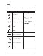
Страница 85: ... v600 Simbolo Significato Definizione Attenzione Consultare la documentazione fornita Tensione pericolosa Attenzione presenza di tensione pericolosa Simbolo di conformità CE Il prodotto è conforme ai requisiti richiesti dalle direttive CE applicabili Acceso Spento Corrente continua CC Corrente alternata CA Corrente continua in volt Ampere ...

Страница 86: ...me una luce per attraversare un ambiente buio Pericoli elettrici Non immergere mai alcuna componente del sistema in acqua o altri liquidi Usare solo prese di corrente approvate e collegate con la terra Evitare il contatto di oggetti metallici o di qualsiasi parte del corpo con le connessioni elettriche Non usare mai alcun altra fonte di alimentazione con questo sistema I danni risultanti dal ricor...

Страница 87: ... ordinazione 1 Cuffia v300 Z2001 00 Kit del modulo d illuminazione v300 Z2074 00 2 Cavo superiore di alimentazione con Z1762 00 corrente continua 3 Modulo di controllo dell alimentazione Z2076 00 4 Cavo inferiore di alimentazione con Z2079 00 corrente continua 5 Fonte di alimentazione Z2077 00 6 Cavo di alimentazione con corrente alternata 7 Cinghia del modulo di controllo Z1763 00 dell alimentazio...

Страница 88: ...ore di alimentazione con Z2079 00 corrente continua 5 Fonte di alimentazione Z2077 00 6 Cavo di alimentazione con corrente alternata 7 Cinghia del modulo di controllo Z1763 00 dell alimentazione 8 Pulisci lenti IMPORTANTE La Syris Scientific non è responsabile per i danni risultanti nel corso della spedizione Se si constata la presenza di danni al momento della consegna informare immediatamente la ...

Страница 89: ...riore sia collocato confortevolmente al di sopra delle sopraciglia Se la cuffia è sistemata troppo in alto o troppo in basso sulla testa ripetere le operazioni descritte al punto uno 4 Serrare spingendo il pomello sul retro della cuffia e girandolo in senso orario 5 Regolare la posizione dello schermo visivo ruotando i pomelli che si trovano su entrambi i lati della cuffia Le lenti d ingrandimento so...

Страница 90: ...rire il connettore IEC del cavo di uscita della corrente alternata nella porta IEC sulla fonte di alimentazione 6 Inserire la spina del cavo di uscita della CA in una presa approvata Dopo aver completato la procedura di messa a punto della connessione dei cavi girare l interruttore del modulo di controllo dell alimentazione in posizione di acceso Si deve udire immediatamente la ventola del modulo ...

Страница 91: ...do si indossa la cuffia localizzare il modulo d illuminazione con la mano libera 2 Far scivolare la propria mano in basso lungo il modulo d illuminazione fino a localizzare il picchetto di regolazione situato sulla parte anteriore del tubo 3 Afferrare delicatamente il picchetto di regolazione e ruotarlo come mostrato nella Figura 4 4 Quando la cuffia è fissata sulla testa la modalità di superficie pola...

Страница 92: ... un display della condizione del Modulo d illuminazione 1 in Fig 1 Tre LED colorati sono installati per essere visibili attraverso gli sbocchi di ventilazione sul retro dell illuminatore Verde Rimane visibile per il primo 75 della sua durata di servizio Giallo Indicata che rimane 5 24 della sua durata di servizio A questo punto è suggerito di ordinare il ricambio Rosso Indica che rimane meno del 5...

Страница 93: ...eddare il vecchio modulo d illuminazione per almeno dieci minuti prima di procedere 3 Allentare i galletti di plastica su ogni lato del vecchio modulo d illuminazione di circa un giro e rimuovere il modulo dal telaio della cuffia 4 Installare il nuovo modulo d illuminazione sul telaio della cuffia e serrare i galletti di plastica 5 Connettere il cavo superiore di alimentazione con corrente continua ...

Страница 94: ...Con la mano guantata rimuovere il nuovo modulo dall avvolgimento in plastica IMPORTANTE Non permettere che la lampadina o il riflettore del modulo d illuminazione entrino in contatto con la cute non protetta o con materiali esterni per evitare guasti prematuri del modulo d illuminazione 6 Installare il nuovo modulo d illuminazione nel tubo ottico avvitandolo in senso orario IMPORTANTE Non forzare i...

Страница 95: ...opo qualsiasi uso che possa aver provocato una contaminazione Pulire il prodotto intero col disinfettante contenere di di towelettes o towelettes l alcool di isopropyl di approvato Non pulire mai le parti dell apparecchiatura con oggetti duri o abrasivi Dopo aver eseguito la pulizia si raccomanda di pulire delicatamente le lenti d ingrandimento e lo schermo visivo con un panno per parti ottiche o ...

Страница 96: ... o v600 Numero di ordinazionee Descrizione Z1924 00 Sistema di visualizzazione v600 Z2001 00 Sistema di visualizzazione v300 Z2073 00 Kit del modulo d illuminazione v600 Z2074 00 Kit del modulo d illuminazione v300 Z2075 00 Schermo visivo con lenti a 3 diottrie ingrandimento di 1 75 volte Z2076 00 Modulo di controllo dell alimentazione Z2077 00 Fonte di alimentazione v300 v600 Z2079 00 Cavo inferi...

Страница 97: ...arti difettose L involucro esterno e le parti cosmetiche devono risultare senza difetti al momento della consegna e pertanto non saranno coperte da questa garanzia limitata 4 A richiesta della Syris Scientific il consumatore è tenuto a fornire informazioni che provino la data approssimativa dell acquisto 5 Il consumatore si accolla gli oneri e il costo della spedizione alla Syris Scientific in Gray ...

Страница 98: ...no applicate le prassi di normale servizio alla Syris Scientific e al consumatore saranno fatturate tutte le spese di spedizione 10 Tutte le garanzie implicite di commerciabilità o conformità ad un particolare scopo saranno limitate al periodo di validità di questa garanzia scritta Altrimenti la presente garanzia rappresenta la sola ed esclusiva riparazione per il consumatore e sostituisce ogni alt...

Страница 99: ...18 www syrisscientific com Syris Scientific LLC ...

Страница 100: ...ivare la garanzia Riempire il modulo e ritornarlo alla Syris Scientific Si prega di scrivere chiaramente Nome ________________________________________________________________ Indirizzo_______________________________________________________________ ____________________________________________________________________ Telefono Codice di zona ________________________________________________ Fax Codice ...

Страница 101: ......

Страница 102: ...Revisión 3 Julio 2004 Spanish Sistema de visualización v300TM v600TM Manual del propietario ...

Страница 103: ...yrisscientific com Página Web www syrisscientific com Horario de atención del Centro de Servicio lunes a viernes de 8 de la mañana a 5 de la tarde hora del este de EE UU Representante europeo autorizado CEpartner4U BV Esdoornlaan 13 3951DB Maarn The Netherlands Teléfono 31 0 343 442 524 Cell 31 0 6 516 536 26 Fax 31 0 343 442 162 Correo electrónico office cepartner4u nl Contact Theo Nusselder Harry T...

Страница 104: ... instrucciones de cuidado y de uso contenidas en este manual No vacile en llamar a nuestro grupo de servicio al 207 657 7050 si podemos ayudarlo a usar su nuevo sistema Syris Scientific LLC Table of Contents Símbolos 4 Advertencias de seguridad y riesgos 5 Descripción del producto 6 Instalación del producto 8 Uso del producto 10 Reemplazo del iluminador 11 Manejo limpieza y almacenamiento 14 Especi...

Страница 105: ...v300 y v600 Símbolo Título Definición Atención Consultar los documentos que vienen con el producto Voltaje peligroso Advertencia voltaje peligroso presente Marca de conformidad CE El producto cumple con los requisitos de las directivas aplicables de la UE Encendido Apagado Corriente Directa DC Alternating Current AC Voltios Corriente Directa Amperios ...

Страница 106: ... No use el sistema como una luz para iluminar su entorno Peligros eléctricos Jamás sumerja los componentes del sistema en agua ni otros líquidos Utilice únicamente una toma de corriente autorizada conectada a tierra Evite el contacto de objetos metálicos o partes del cuerpo con las conexiones eléctricas No utilice una fuente de alimentación distinta con la unidad Los daños resultantes del uso de u...

Страница 107: ... Código de pedido 1 Soporte de cabeza v300 Z2001 00 v300 Conjunto del módulo Iluminador Z2074 00 2 Cable superior de alimentación de corriente Z1762 00 directa DC 3 Módulo de control de alimentación Z2076 00 4 Cable inferior de alimentación de corriente Z2079 00 directa DC 5 Alimentación Z2077 00 6 Cable de alimentación de corriente alterna AC 7 Correa del módulo de control de alimentación Z1763 0...

Страница 108: ...6 00 4 Cable inferior de alimentación de corriente Z2079 00 directa DC 5 Alimentación Z2077 00 6 Cable de alimentación de corriente alterna AC 7 Correa del módulo de control de alimentación Z1763 00 8 Limpiadores de la lente IMPORTANTE Syris Scientific no se responsabiliza por los daños que ocurran durante el transporte Si su sistema llega dañado llame inmediatamente a la compañía de transporte par...

Страница 109: ...oj 3 Póngase el soporte en la cabeza asegurando que el frente de la banda para la cabeza le caiga cómodamente encima de las cejas Si el soporte le queda demasiado alto o demasiado alto en la cabeza repita el primer paso 4 Ajuste la banda para la cabeza empujando la perilla en la parte de atrás de la banda para la cabeza y haciéndola girar en el sentido de las agujas del reloj 5 Ajuste la posición ...

Страница 110: ...hufe el conector IEC del cable de alimentación AC al puerto IEC en la fuente de alimentación 6 Enchufe el enchufe AC del cable de alimentación AC a un enchufe aprobado Después de completar la instalación del cableado ponga el interruptor del módulo de control de alimentación en posición de encendido Debe oír inmediatamente que se enciende el ventilador del módulo iluminador Para prevenir un choque...

Страница 111: ...nstrucciones sencillas 1 Con el soporte de la cabeza puesto ubique el módulo iluminador con la mano libre 2 Deslice la mano por el módulo iluminador hacia abajo hasta encontrar la pieza de ajuste ubicada en el frente del tubo 3 Tome suavemente la pieza de ajuste y hágala girar como se demuestra en la Figura 4 Ajuste de la polarización Al tenerse puesto en la cabeza la modalidad de superficie polari...

Страница 112: ...ión de la condición del Módulo iluminador 1 en Fig 1 Hay tres LEDs coloreados instalados para que sean visibles a través de las entradas de aire en la parte trasera del iluminador Verde Permanece visible durante el primer 75 de la duración esperada Amarillo Indica que queda entre el 5 y el 24 de la duración esperada Se sugiere que se pida un reemplazo cuando pasa a estar en amarillo Rojo Indica qu...

Страница 113: ... minutos antes de continuar 3 Afloje las tuercas mariposa plásticas a los lados del iluminador viejo aproximadamente una vuelta y retírelo del marco del soporte para la cabeza 4 Instale el nuevo módulo iluminador en el marco del soporte para la cabeza y ajuste las tuercas mariposa de plástico 5 Conecte el cable de alimentación superior DC al módulo iluminador y enchufe el cable de alimentación de e...

Страница 114: ...iluminador nuevo de su envoltorio de plástico Aviso importante No permita que la bombilla del módulo iluminador o el reflector entren en contacto con la piel o con otro material foráneo Ello puede causar el fallo prematuro del Módulo iluminador 6 Instale el nuevo módulo iluminador en el tubo óptico atornillándolo en el sentido de las agujas del reloj Aviso importante No fuerce el nuevo módulo ilumi...

Страница 115: ... del producto Limpieza Limpie el sistema después de cada uso que pueda haber causado contaminación Limpie el producto entero con towelettes aprobado de desinfectante o alcohol de isopropyl de contener de towelettes Jamás limpie los componentes del sistema con objetos duros o abrasivos Se recomienda que después de limpiar el sistema se pase un paño óptico o un paño equivalente no abrasivo y sin pel...

Страница 116: ...300 ó v600 Código de pedido Code Descripción Z1924 00 v600 Sistema de visualización Z2001 00 v300 Sistema de visualización Z2073 00 v600 Conjunto del módulo iluminador Z2074 00 v300 Conjunto del módulo Iluminador Z2075 00 Lente Visi Shield de 3 dioptrías ampliación 1 75 Z2076 00 Módulo de control de alimentación Z2077 00 v300 v600 Fuente de alimentación Z2079 00 Cable inferior de alimentación de c...

Страница 117: ... carcasa externa y las piezas de adorno estarán libres de defectos al salir de fábrica y por lo tanto no estarán cubiertas por las condiciones de esta garantía limitada 4 Si se lo solicita Syris Scientific el Consumidor deberá proporcionar información que pruebe razonablemente la fecha de compra 5 Los costes de envío y los aranceles aduaneros que incurra Syris Scientific en Gray Maine EE UU correrán...

Страница 118: ...lverá con porte a cobrar Si el Producto se devuelve a Syris Scientific después del vencimiento del período de garantía se aplicarán las normas habituales de servicio y se cobrarán los gastos de envío al Consumidor 10 Toda garantía implícita de comercialización o aptitud para un fin o uso determinado estará limitada a la duración de la garantía por escrito que antecede De lo contrario la garantía que...

Страница 119: ...s o responsabilidades aparte de las que se contemplan expresamente en esta garantía limitada Se cobrará al Consumidor el importe de las piezas o los gastos de mano de obra que no estén cubiertos por esta garantía limitada 13 Las garantías de los accesorios y complementos suministrados por Syris Scientific se describen específicamente en sus propias tarjetas de garantía y embalaje ...

Страница 120: ...Syris Scientific LLC Escriba claramente Nombre y apellido _________________________________________________________ Dirección ______________________________________________________________ ____________________________________________________________________ Teléfono Código de área ________________________________________________ Fax Código de área __________________________________________________ ...

Страница 121: ......
Отзывы:

Похожие инструкции для v300TM