


OPERATING MODES
PAGE
|
47
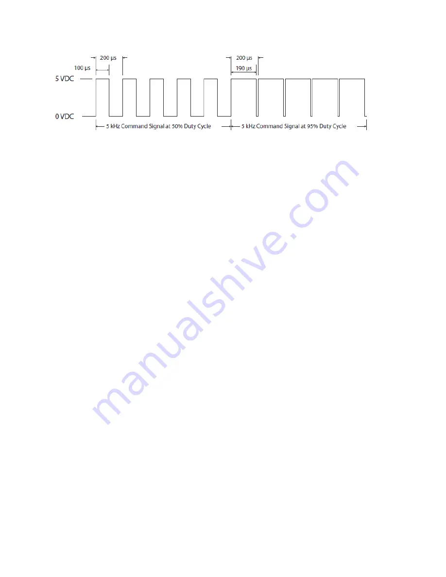
Figure 4-4 PWM signal waveform.
Gated operation
In many marking and cutting applications, the laser is required to pulse, or gate, on and off in
synchronization with an external control signal (typically from a computer or function generator
operating in the range from DC to 1 kHz). To pulse or gate the laser, connect a signal pro5.0 VDC
pulses to the Gate connector on the rear panel of the UC-2000.
Users who intend to use a gating signal should set the UC-2000’s gate input logic to internal Pull-Down
(normally off) mode. This prevents the beam from being enabled unless a high level (+3.5 V to +5.0
VDC) signal is applied to the Gate input connector. In the pull-down (normally off) mode, an asserted
logic low signal, short circuit to ground, or an open or disconnected Gate input locks the beam off.
Many CO
2
lasers operating in applications requiring short gating pulses at repetition rates below 500 Hz
will exhibit some leading-edge overshoot regardless of the PWM frequency. This occurs because a
cooler lasing medium (the CO
2
gas) is more efficient than a hotter one. The overshoot effect is more
pronounced at lower gating frequencies since the gas has a longer time to cool down between
Command signal pulses.
NOVANTA ti-Series lasers produce an optical output pulse that is almost exactly square (see the figure
below), meaning that there is no leading-edge overshoot and virtually no power variation across the
actual pulse. The square output pulse of the ti-Series laser coupled with its shorter rise times (~75
μ
s)
means that material processing is more efficient since a greater amount of laser energy is absorbed,
which is especially desirable when working with high threshold materials.
Marking/engraving operation
When the delay between the end of one PWM Command signal pulse and the beginning of the next
PWM pulse exceeds 200 microseconds (less than or equal to 5 kHz), your laser’s on-board tickle
generator sends a tickle pulse to maintain plasma ionization in the tube. Because the on-board tickle
generator cannot anticipate when the next PWM Command pulse will arrive, the tickle pulse (which
typically lasts for 2–6
μ
s depending on the laser) can effectively merge with a PWM signal that follows
closely afterwards. When the PWM pulse that follows is short, causing the tickle pulse to become a
significant fraction of the PWM pulse duration, then the tickle pulse effectively substantially increases the
length of the PWM pulse it has merged with. For subtle marking applications on sensitive, low threshold
materials this lengthened PWM pulse may affect mark quality.
While this situation can occur when using PWM Command signal frequencies of 5 kHz and less, it is
important to note that it isn’t the Command signal frequency itself that is the determining factor but
rather this behavior happens only when the off time between PWM pulses exceeds 200 microseconds.
Содержание Novanta OEM ti Series
Страница 1: ...ENGINEERED BY SYNRAD OEM ti Series User Manual...
Страница 26: ...TI60 LABEL LOCATIONS PAGE 26 Ti60 label locations Figure 3 1 Ti60 hazard label locations...
Страница 27: ...TI80 LABEL LOCATIONS PAGE 27 Ti80 label locations Figure 3 2 Ti80 hazard label locations...
Страница 28: ...TI100 LABEL LOCATIONS PAGE 28 Ti100 label locations Figure 3 3 Ti100 hazard label locations...
Страница 32: ...EUROPEAN UNION EU REQUIREMENTS PAGE 32 Table 3 1 Class 4 safety features...
Страница 34: ...EUROPEAN UNION EU REQUIREMENTS PAGE 34 Figure 3 4 ti60 Declaration Document...
Страница 35: ...EUROPEAN UNION EU REQUIREMENTS PAGE 35 Figure 3 5 ti80 Declaration document...
Страница 36: ...EUROPEAN UNION EU REQUIREMENTS PAGE 36 Figure 3 6 ti00 Declaration document...
Страница 52: ...USER I O CONNECTION SUMMARY PAGE 52 Figure 4 5 User I O pinouts Table 4 3 User I O pin descriptions continued...
Страница 55: ...INPUT SIGNALS PAGE 55 Table 4 5 Input signal table continued...
Страница 65: ...DB 9 PIN DESCRIPTIONS PAGE 65 Table 4 9 Side mounted DB 9 pin descriptions continued...
Страница 73: ...REMOTE INTERLOCK FUNCTIONS PAGE 73 Table 4 10 Ti60 general specifications continued...
Страница 74: ...REMOTE INTERLOCK FUNCTIONS PAGE 74 Table 4 11 Ti80 general specifications...
Страница 75: ...REMOTE INTERLOCK FUNCTIONS PAGE 75 Table 4 11 Ti80 general specifications continued...
Страница 76: ...REMOTE INTERLOCK FUNCTIONS PAGE 76 Table 4 12 Ti100 general specifications...
Страница 77: ...REMOTE INTERLOCK FUNCTIONS PAGE 77 Table 4 12 Ti100 general specifications continued...
Страница 79: ...TECHNICAL DRAWINGS PAGE 79 Figure 4 26 Fan cooled ti60 ti80 package outline and mounting dimensions...
Страница 82: ...TECHNICAL DRAWINGS PAGE 82 Figure 4 29 Ti Series HS Outline and Mounting...
Страница 83: ...TECHNICAL DRAWINGS PAGE 83 Figure 4 28 Ti 100p Outline and Mounting...
Страница 84: ...TECHNICAL DRAWINGS PAGE 84 Figure 4 29 Ti 100 Fan Outline and Mounting...
Страница 85: ...TECHNICAL DRAWINGS PAGE 85 Figure 4 30 ti Series packaging instructions...
Страница 93: ...MAINTENANCE TROUBLESHOOTING PAGE 93 Table 4 14 Status Signals...
Страница 99: ...MAINTENANCE TROUBLESHOOTING PAGE 99...
Страница 105: ...APPENDIX PAGE 3 This page is intentionally left blank...


