Section IV
Multiple UPS Configurations
006-0007129 10/12/2018
Rev B
37 of 60
UPS-1500 3-Phase Guide
www.synqor.com
Parallel Connection of the AC OUTPUTS
Multiple UPS units can have their AC OUTPUTS connected in parallel to deliver to the load the
sum of their combined output power and current. This configuration also allows redundant
parallel units (type “R”) to form N+1 or N+M redundant systems.
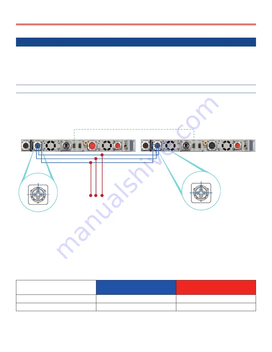
Two UPS units with AC OUTPUTS Paralleled
The following diagram shows how to connect two UPS OUTPUTS in a standard or extended
redundant parallel configuration. The wiring diagram explains how the AC OUTPUT cables and
the CONFIGURATION cable need to be connected:
L1
N
PEGND
L1
N
PEGND
L1 N
TO LOAD
PEGND
AC OUTPUT
AC OUTPUT
REAR PANEL
REAR PANEL
CONFIGURATION cable SYN-9311 or SYN-9341
When ordering, select the “F: Floating” or “R: Redundant” option for UPS units configured
in this manner. Use CONFIGURATION cable SYN-9311 for standard “F” type parallel and SYN-
9341 for expanded redundant “R” type parallel units.
If the user is providing the AC OUTPUT cable, the cable size for the blue and red sections
shown above should follow the guide lines in the table below depending on the output voltage
configuration of the UPS units.
UPS AC OUTPUT Voltage
Blue Cable Section
Minimum Wire Size
Red Cable Section
Minimum Wire Size
115 Vac
#14 AWG (2.5 mm
2
)
#10 AWG (6mm
2
)
230 Vac
#16 AWG (1.5 mm
2
)
#12 AWG (4mm
2
)


