E12 Physical Interfaces
The E12 includes a tri-color LED that you can control from your programs, plus a button you can monitor. Control
scripts in the E12-led and E12-button packages assist with controlling the LED and monitoring the button.
E12 LEDs
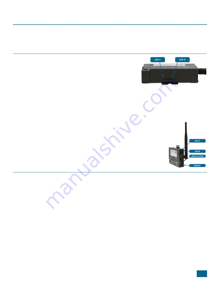
The four processor-controlled LEDs are single color - green - and by
default are activity indicators. The LEDs are numbered 1 - 4 proceeding
from left to right. You can set the LED state using the following commands:
l
led-1 on / led-1 off
l
led-2 on / led-2 off
l
led-3 on / led-3 off
l
led-4 on / led-4 off
l
led-a [red | green | amber | off]
led1 is closest to the terminal blocks and is labeled "1".
An additional LED is on the side of the E12 next to the antenna. This LED, known as LED A, is
controlled via the Linux instance running on the E12. The other LED, LED B, is controlled via
the SNAPpy script running on the internal SM220 module.
Finally, there are two LEDs on the E12 ethernet port. A green LED that indicates the E12 is
connected to the network, and a yellow LED that illuminates when the E12 is configured for
100Mbps communications.
The SNAP Module-Controlled LED
The unit's SNAP module controls the tri-color LED on the antenna side of the case (LED A) via GPIO_1 (green) and
GPIO_0 (red). (For amber, use both green and red.) This LED is only accessible via the SNAP module. It cannot be
controlled by the E12’s AM335x processor, except through calls to the SNAP module.
These two IO lines from the SNAP module will light their respective colors when written high. This sample code
demonstrates its use:
from synapse.platforms import *
GREEN=GPIO_1
RED=GPIO_0
@setHook(HOOK_STARTUP)
def onStartup():
setPinDir(RED, True)
11
Содержание SNAPconnect E12
Страница 30: ...26 SNAPconnect E12 User Guide 116 081614 030 B001 E12 Dimensions ...
Страница 34: ......
Страница 35: ......


