


2.
Setting Up Your SNAP Link Wireless Adapters
Refer to
your SNAP Link Quick Start Guide accompanying your SNAP Link wireless adapter for illustrations
showing you how to set it up quickly. This chapter gives you more detail about the various modes of operation
and the three indicator lights.
Modes of Operatio
n
SNAP Link units are powered via a USB cable through their micro
-
B USB connector. They can be powered by
connecting a USB cable to the supplied AC adapter, or by plugging the cable into the USB port of a computer. It
will be necessary to use a computer’s USB port if you wish to configure your SNAP Link units using the EasySet
software, which is described in the next chapter.
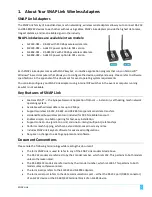
All models of SNAP Link can operate in either point-to-
point mode, also known as unicast, or in multipoint mode,
also known as multic
ast. In point-to-
point mode two SNAP Link units are paired, thereby providing a wireless
connection between two external serial devices. In multipoint mode, one of the SNAP Link devices is designated
the master and multiple other devices can be configured as slaves. This section provides more detail on how
these modes can be set manually by pressing the MODE button on the SNAP Link device.
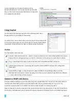
SNAP Link State Indicators
You can change the state of your adapter either by holding down the MODE button or by pressi
ng it in rapid
succession.
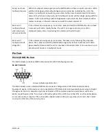
There are three LEDs on a SNAP Link device. LED A is located on the front next to the MODE button. LEDs B and C
are located on the back panel between the micro
-
B USB and serial connectors.
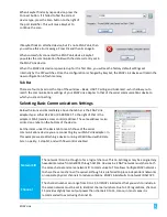
Set from the factory, these three LEDs c
ommunicate various configuration settings or traffic status events as
documented next, unless the Modbus firmware script has been uploaded to the SNAP Link adapter.
Note:
The three LEDs perform differently when the Modbus hardened reliability firmware has been
installed, as documented in the Modbus Firmware Appendix
The A LED indicates the wireless broadcast state. It can be off, green, amber or red, and can be steady or flashing
depending upon the current status or mode of operation:
•
When the unit is seeki
ng a pair the LED will rapidly flash red.
•
When the unit is paired, either in unicast mode or as a slave in multicast mode, the LED will glow
steadily. Green indicates a strong wireless signal, amber indicates a weak signal, and red indicates no
signal or l
oss of signal from its partner. No matter what the color, the LED will flicker while wireless
transmission is occurring.
•
When the unit is in multipoint mode and is seeking a master, the LED will rapidly flash amber.
•
When the unit is set up as a master, the
LED will slowly alternate between green and amber.
•
If a master detects another master on the same channel and network, the LED will slowly alternate
between red and amber.
The B LED indicates the USB state. Green indicates the unit is being supplied with power. It will glow steadily in
idle and will flicker when data is being transferred via the USB port.
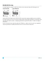
The C LED indicates the serial interface state. If an RS
-
232 device is attached to the DB9F connector of the SL232
adapter, the LED will glow steadily green in idle and will flicker as data is being transferred. If an RS
- 484/422
SNAP Link
3
Содержание SNAP Link
Страница 4: ......