


1.
About Your SNAP Link Wireless Adapters
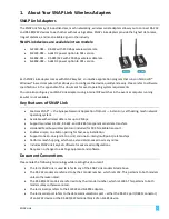
SNAP Link Adapters
The SNAP Link family of industrial
-
class, mesh networking, wireless serial adapters allows you to connect RS
-232
and RS-
485/422 devices to each other without using cable
s. SNAP Link adapters provide the highest data-rates,
longest distance, and most reliable signal in the industry.
SNAP Link devices are available in two models:
•
SL232K-001 – RS-
232 with 250 Kbps wireless data rate
•
SL232K-002 – A
dds DC power option to 001 vers
ion
•
SL485K-001 – RS-
485/422 with 250 Kbps wireless data rate
•
SL485K-002 –
Adds DC power option to 001 version
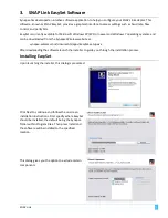
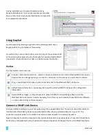
Each SNAP Link adapter comes with SNAP EasySet, an intuitive application program that runs on Microsoft®
Windows®
-
based computers that allows you to configure the device quickly and easily. Please refer to software
specifications in the appendix of this document for exact operating system requirements.
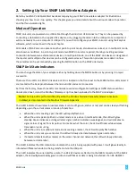
You can also configure your SNAP Link adapters using internal DIP switches in the event a computer running
EasySet is not available.
Key Features of SNAP Link
•
Features SNAP®
— the Synaps
e Network Application Protocol
— instant-on, self-
healing, mesh network
operating system.
•
Available with wireless data rates up to 2 Mbps.
•
Supports wireless RS
-232, RS-422, and RS-485 transparent serial data transfers.
•
Hardened Modbus wireless protocol included for 99.5% reliable transport.
•
Enables simple, one button pairing for fast, easy installation.
•
Supports one-to-one (point-to-point) and one-to-
many (multipoint) relationships.
•
Performs mesh hopping, which can extend distances across many miles.
•
Includes SNAP Link EasySet software for advanced configurations.
•
Requires no changes to existing equipment and software.
Document Conventions
Please note the following terminology while reading this document:
•
The term SNAP Link is used to refer to any of the SNAP Link models listed above.
•
The RS
-
232 models are referred to by their model number, which is SL232. This pertains to both models
unless otherwise noted.
•
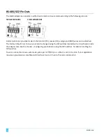
The RS
-
485/422 models are referred to by their model number, which is SL485. This pertains to bo
th
models unless otherwise noted.
•
The term K
-series refers to the SL232K and SL485K adapters.
•
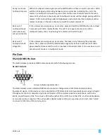
The term serial port refers to the data communications port
– either the RS-
232 port (DB9F connector)
of an SL232 device or the RS-
485/422 terminal block of an SL485 device.
SNAP Link
1
Содержание SNAP Link
Страница 4: ......