5-17
Operating the PDT 6100 Series
To communicate with a host through the CCC (refer to
1. Plug the CCC‘s 10-pin RJ41 connector in the 6100’s base.
2. Connect the DB-9 connector to the host’s serial (COMM) port.
3. Start the communications program on the host and the 6100.
Figure 5-9. Using the CCC to Connect the PDT 6100
to a Host PC (shown) or Printer
Radio Communications
The PDT 6110 operates in a Symbol Spectrum One RF network; the PDT 6140 operates in
a Symbol Spectrum24 RF network.
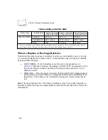
The Status LED indicates the state of the 6100’s connection to either of the RF networks:
Refer to the network documentation for more information on operating the PDT 6100 in the
specific RF environment.
Off
indicates that the radio is working and associated with an access point
(Spectrum24) or base station (Spectrum One).
(The Status LED indication of RF activity is presently not available.)
Flashing green
once per second
indicates that the radio is out of range or not associated with an access point or
base station.
(The Status LED indication of RF activity is presently not available.)
33222013.eps
RJ41
Connector
CCC
DB-9
Connector
Содержание PDT 6100
Страница 1: ...PDT 6100 Series Product Reference Guide ...
Страница 2: ...PDT 6100 Series Product Reference Guide 70 33222 02 Revision A June 2001 ...
Страница 19: ...1 6 PDT 6100 Product Reference Guide ...
Страница 31: ...3 8 PDT 6100 Product Reference Guide ...
Страница 61: ...6 10 PDT 6100 Product Reference Guide ...
Страница 75: ...7 14 PDT 6100 Product Reference Guide ...
Страница 77: ...A 2 PDT 6100 Product Reference Guide ...
Страница 93: ...D 2 PDT 6100 Product Reference Guide ...
Страница 105: ...Index 6 PDT 6100 Product Reference Guide ...
Страница 107: ......

