


1-2-4
SFTY_2
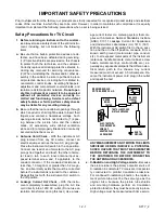
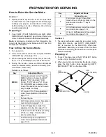
Safety Check after Servicing
Examine the area surrounding the repaired location
for damage or deterioration. Observe that screws,
parts and wires have been returned to original posi-
tions. Afterwards, perform the following tests and con-
firm the specified values in order to verify compliance
with safety standards.
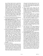
1. Clearance Distance
When replacing primary circuit components, confirm
specified clearance distance (d) and (d') between sol-
dered terminals, and between terminals and surround-
ing metallic parts. (See Fig. 1)
Table 1 : Ratings for selected area
Note: This table is unofficial and for reference only.
Be sure to confirm the precise values.
2. Leakage Current Test
Confirm the specified (or lower) leakage current be-
tween B (earth ground, power cord plug prongs) and
externally exposed accessible parts (RF terminals,
antenna terminals, video and audio input and output
terminals, microphone jacks, earphone jacks, etc.).
Measuring Method : (Power ON)
Insert load Z between B (earth ground, power cord
plug prongs) and exposed accessible parts. Use an
AC voltmeter to measure across both terminals of
load Z. See Fig. 2 and following table.
Table 2 : Leakage current ratings for selected areas
Note: This table is unofficial and for reference only. Be sure to confirm the precise values.
AC Line Voltage
Region
Clearance
Distance (d) (d')
110 to 130 V
USA or
CANADA
≥
3.2 mm
(0.126 inches)
Chassis or Secondary Conductor
d
d’
Primary Circuit Terminals
Fig. 1
Fig. 2
AC Voltmeter
(High Impedance)
Exposed Accessible Part
B
One side of
Power Cord Plug Prongs
Z
AC Line Voltage
Region
Load Z
Leakage Current (i)
Earth Ground (B) to:
110 to 130 V
USA or
CANADA
0.15
µ
F CAP. & 1.5k
Ω
RES. connected in
parallel
i
≤
0.5mA rms
Exposed accessible
parts
Содержание SRC2213
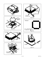
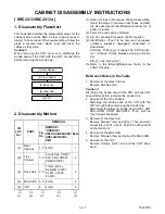
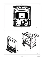
Страница 20: ...1 6 2 T5307DC Fig 1 S 1 S 1 1 REAR CABINET S 1 S 1 S 1 S 1 Fig 2 ...
Страница 21: ...1 6 3 T5307DC S 2 S 4 S 3 S 3 S 4 S 4 S 4 S 4 S 2 S 2 S 2 2 TRAY CHASSIS 4 MAIN CBA 3 DECK UNIT Fig 3 ...
Страница 22: ...1 6 4 T5307DC Fig 4 CRT CBA S 5 S 5 S 5 S 5 ANODE CAP 5 CRT ...
Страница 25: ...1 6 7 T7308DC Fig 1 ANT S 1 S 1 1 REAR CABINET S 1 S 1 S 1 S 1 Fig 2 ...
Страница 26: ...1 6 8 T7308DC S 2 S 4 S 3 S 3 S 4 S 4 S 4 S 4 S 2 S 2 S 2 2 TRAY CHASSIS 4 MAIN CBA 3 DECK UNIT Fig 3 ...
Страница 27: ...1 6 9 T7308DC Fig 4 S 5 S 5 S 5 S 5 5 CRT CRT CBA ANODE CAP ...
Страница 88: ...Packing SRC2213 SRC22134 FRONT X 4 X 3 X 2 TAPE X 1 S 1 X 5 S 4 S 6 S 2 S 3 S 3 S 2 3 1 5 T5307PEX ...
Страница 89: ...Packing SRC22194 X 1 S 1 S 4 S 3 S 3 S 2 TAPE TAPE X 4 X 3 X 2 S 6 S 14 FRONT 3 1 6 T7308PEX ...
Страница 108: ...Printed in Japan 2002 02 20 HO SRC2213 SRC22134 SRC22194 T5307UH 8UJ 7308UJ ...