


2-3-4
T5307MA
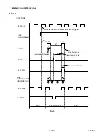
6. Press CH DOWN button on the unit until the CTL
waveform has shifted from its original position (not
the position achieved in step 5, but the position of
CTL waveform in step 4) by approximately -2msec.
Make sure that the envelope is simply attenuated
(shrinks in height) once CTL waveform passes its
original position and is further brought in the minus
direction.
7. Set the Tracking Control Circuit to the center posi-
tion by pressing CH UP button and then “ PLAY ”
button on the unit.
1-C. Checking/Adjustment of Envelope
Waveform
Purpose:
To achieve a satisfactory picture and precise tracking.
Symptom of Misalignment:
If the envelope output is poor, noise will appear in the
picture. The tracking will then lose precision and the
playback picture will be distorted by any slight varia-
tion of the Tracking Control Circuit.
1. Connect the oscilloscope to J189 (PB-C-MONI) on
the Main CBA. Use J190 (RF-SW) as a trigger.
2. Playback the Gray Scale on the Alignment Tape
(FL8N---[ SRC2213 ],
FL8NW---[ SRC22134/SRC22194 ]).
Set the Tracking Control Circuit to the center posi-
tion by pressing CH UP button and then “ PLAY ”
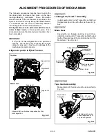
button on the unit. Adjust the height of Guide Roll-
ers [2] and [3] (Fig. M3, Page 2-3-3) watching the
oscilloscope display so that the envelope becomes
as flat as possible. To do this adjustment, turn the
top of the Guide Roller with the Guide Roller Adj.
Screwdriver.
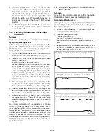
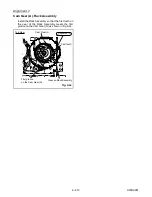
3. If the envelope is as shown in Fig. M7, adjust the
height of Guide Roller [2] (Refer to Fig. M3) so that
the waveform looks like the one shown in Fig. M9.
4. If the envelope is as shown in Fig. M8, adjust the
height of Guide Roller [3] (Refer to Fig. M3) so that
the waveform looks like the one shown in Fig. M9.
5. When Guide Rollers [2] and [3] (Refer to Fig.M3)
are aligned properly, there is no envelope drop
either at the beginning or end of track as shown in
Fig. M9.
Note: Upon completion of the adjustment of Guide
Rollers [2] and [3] (Refer to Fig. M3), check the X
Value by pushing the CH UP or DOWN buttons alter-
nately, to check the symmetry of the envelope. Check
the number of pushes to ensure center position. The
number of pushes CH UP button to achieve 1/2 level
of envelope should match the number of pushes CH
DOWN button from center. If required, redo the “X
Value Alignment.”
1-D. Azimuth Alignment of Audio/Control/
Erase Head
Purpose:
To correct the Azimuth alignment so that the Audio/
Control/Erase Head meets tape tracks properly.
Symptom of Misalignment:
If the position of the Audio/Control/Erase Head is not
properly aligned, the Audio S/N Ratio or Frequency
Response will be poor.
1. Connect the oscilloscope to the audio output jack
on the rear side of the deck.
2. Playback the alignment tape
(FL8N---[ SRC2213 ],
FL8NW---[ SRC22134/SRC22194 ])
and confirm that the audio signal output level is
8kHz.
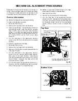
3. Adjust Azimuth Adj. Screw so that the output level
on the AC Voltmeter or the waveform on the oscil-
loscope is at maximum. (Fig. M6)
Dropping envelope level at the beginning of track.
Fig. M7
Dropping envelope level at the end of track.
Fig. M8
Envelope is adjusted properly. (No envelope drop)
Fig. M9
Содержание SRC2213
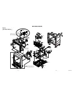
Страница 20: ...1 6 2 T5307DC Fig 1 S 1 S 1 1 REAR CABINET S 1 S 1 S 1 S 1 Fig 2 ...
Страница 21: ...1 6 3 T5307DC S 2 S 4 S 3 S 3 S 4 S 4 S 4 S 4 S 2 S 2 S 2 2 TRAY CHASSIS 4 MAIN CBA 3 DECK UNIT Fig 3 ...
Страница 22: ...1 6 4 T5307DC Fig 4 CRT CBA S 5 S 5 S 5 S 5 ANODE CAP 5 CRT ...
Страница 25: ...1 6 7 T7308DC Fig 1 ANT S 1 S 1 1 REAR CABINET S 1 S 1 S 1 S 1 Fig 2 ...
Страница 26: ...1 6 8 T7308DC S 2 S 4 S 3 S 3 S 4 S 4 S 4 S 4 S 2 S 2 S 2 2 TRAY CHASSIS 4 MAIN CBA 3 DECK UNIT Fig 3 ...
Страница 27: ...1 6 9 T7308DC Fig 4 S 5 S 5 S 5 S 5 5 CRT CRT CBA ANODE CAP ...
Страница 88: ...Packing SRC2213 SRC22134 FRONT X 4 X 3 X 2 TAPE X 1 S 1 X 5 S 4 S 6 S 2 S 3 S 3 S 2 3 1 5 T5307PEX ...
Страница 89: ...Packing SRC22194 X 1 S 1 S 4 S 3 S 3 S 2 TAPE TAPE X 4 X 3 X 2 S 6 S 14 FRONT 3 1 6 T7308PEX ...
Страница 108: ...Printed in Japan 2002 02 20 HO SRC2213 SRC22134 SRC22194 T5307UH 8UJ 7308UJ ...


