


edge to help camera focus operation.
Set
USER CONFIG
Focus Assist
item to enable the focus assist function. The
intensified edges are those areas whose difference value exceeds the reference
focus level (
SENSITIVITY
), and the intensified edge are displayed in the designated
color set by
Focus Assist Color
.
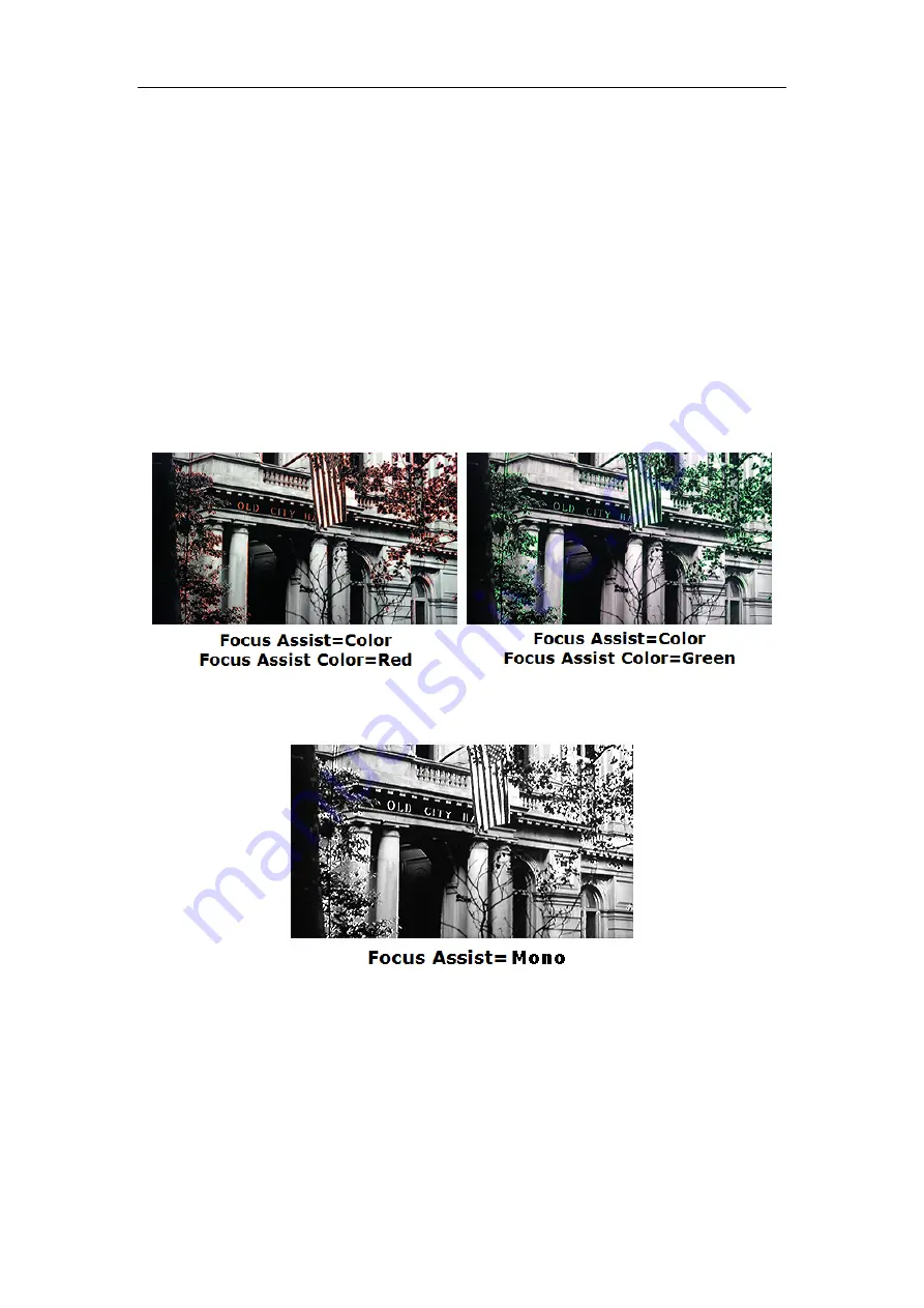
FOCUS ASSIST MODE
Color Mode
: Set
USER CONFIG
Focus Assist
item as
Color
,
the image is in color mode, then set
USER CONFIG
Focus
Assist
Color
to color the intensified edge.
Gray Mode
: Set
USER CONFIG
Focus Assist
item as
Mono
,
the image is in black and white mode, that is removing all colors
and only leaving the luminance data of the signal.
Figure 5.1-21 Illustration for FOCUS ASSIST Function
Figure 5.1-22 Illustration for FOCUS ASSIST Function
FALSE COLOR-Exposure Assist
FALSE COLOR is also known as EXPOSURE ASSIST, this function generates an
artificial luminance map of the input signal that can be useful to identify over exposed
areas(exposure). This is a quick way to gauge the exposure levels of an image in a
clear way.
Содержание FM-21HDR
Страница 5: ...2 Installation Dimension Front Panel Side View Rear Panel Top View...
Страница 6: ...3 Installation instructions of accessories Desktop Stand Feet...
Страница 7: ...Sun hood Potective Glass...
Страница 51: ...51...


