7
CUTTER HEIGHT ADJUSTMENT
•
There is approximately 4” of height adjustment.
•
Rotate height adjust crank handle in a clockwise direction to lower the mower deck.
Rotate counterclockwise to lift the mower deck.
•
Dense areas should be cut twice.
•
Push handle down to lock height position.
TOW HITCH OFFSET
•
When offsetting the cutter do so to the side opposite the discharge of the tow
vehicle.
•
Swisher recommends if the tow vehicle is equipped with a mid-mount mower to
overlap the cut approximately 6”. This may vary depending on mowing terrain,
obstacles, and/or tow vehicle. Always keep safety the first priority.
•
Always keep the tow vehicle cutter raised higher than the Trail Cutter.
STARTING TO CUT
•
Adjust the cutting height.
•
Double check vehicle to cutter attachment.
•
Start mower engine and set throttle to “FAST” for best cutting performance.
•
Slowly engage T-handle lever. See Fig 8 pg 16.
•
Carefully mount tow vehicle and start mowing at a slow travel speed.
STOPPING THE CUTTING SESSION
•
Bring tow vehicle to a complete stop, set the parking brake and disengage blades.
•
Turn key switch to the “OFF” position.
•
Always remember to remove keys to avoid irresponsible usage.
SUGGESTED CUTTING PRACTICES
•
Operate cutter engine at full throttle to assure the best cutting performance and
maximum material discharge.
•
Allow wet grass to dry. Wet grass will clump and collect under the mowing deck.
•
Cutter should be started with tow vehicle in low gear and increased only as safe
mowing conditions permit. Cutting speed should not exceed 5 MPH.
•
Cutting conditions and the types of grass will vary from place to place. You may
find when cutting dense areas that the pressure of the wheel tracks may cause the
grass to be pushed down and not effectively mowed. If this happens you may want
to mow the area twice. Once with the cutter raised and the second cutting at the
desired height. The second cutting should be at a right angle from the previous for
best results.
Содержание QBRC14544
Страница 17: ...WIRING DIAGRAM 11 5HP ENGINE FIGURE 9 17 WIRING DIAGRAM 14 5HP ENGINE FIGURE 10 10299 19193...
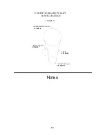
Страница 18: ...Notes 18 FIGURE 11 ENGINE TO BLADE PULLEY CONFIGURATION P N B527 P N 4846 P N BB105 P N BA50...
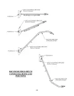
Страница 20: ...RECOMMENDED HITCH CONFIGURATIONS AND POSITIONS 20...
Страница 21: ...21...


