6
ENGAGING BLADES
Note: Do not attempt to start the unit with the T-handle console in the “ENGAGED” position.
• Engage blades by pulling down the T-handle lever into the horizontal position.
• Return lever to the vertical position to disengage blades. See Fig 8 pg 16.
•The braking system is applied when the blades become disengaged. It is designed to bring the blades
to a quick stop (approximately 7 seconds). Each Trail Cutter brake system has been set at the factory
the consumer should not alter any part of the brake system.
BREAKING IN YOUR CUTTER
•
Set the vehicle parking brake and chock the wheels to prevent accidental rolling.
•
While the engine is running, slowly engage blade control.
•
In a safe environment, (i.e. no children or pets) allow blades to rotate and engine to
idle for 5 minutes, breaking in the belt for a longer life.
•
Stop cutter.
FRONT TO BACK ADJUSTMENT
For best cutting results, the cutter deck should be parallel to the ground. To check parallel adjustment,
measure the distance from the bottom edge of the deck in both the front and rear of the deck. This
adjustment is best done while the tow vehicle and Trail Cutter are connected.
•
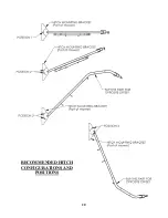
Remove hair pins NB127 from clevis pins 18842 so L-hitch 18829 can be repositioned.
•
Raise or lower hitch section to obtain proper front to back adjustment.
•
Insert clevis pins in the desired hitch position and secure with hair pins.
CAUTION: SHUT OFF THE CUTTER ENGINE AND REMOVE SPARK
PLUG WIRE FROM SPARK PLUG BEFORE MAKING ANY
ADJUSTMENTS TO THE CUTTER.
STARTING THE ENGINE
See engine manufacturer’s recommendations for the type and amount of oil and fuel used. Trail Cutters
equipped with an electric start engine will need a battery (sold separately). Swisher recommends using a
standard “U1” battery.
•
Make sure the tow vehicle parking brake is set, mower is level, and blades are
disengaged. Engine must be level to accurately check and fill oil. Do not overfill.
•
Check spark plug wire, oil, and fuel.
•
Check all electrical connections for buildup of debris.
•
Set engine idle to “CHOKE” position.
•
Turn key to the “RUN” position.
•
Pull rope with a single fluid motion.
•
(12V models only) Turn key to the “RUN” position, then to the “START” position.
•
Set engine idle at maximum RPM for best performance.
•
Allow engine to run a few moments before engaging blades.
IMPORTANT: This engine is not equipped with a spark arrester muffler. It is a violation of
California Public Resource Code Section 4442 to use or operate the engine on any forest-covered,
brush-covered, or grass-covered land. Other states or federal areas may have similar laws.
Содержание QBRC14544
Страница 17: ...WIRING DIAGRAM 11 5HP ENGINE FIGURE 9 17 WIRING DIAGRAM 14 5HP ENGINE FIGURE 10 10299 19193...
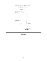
Страница 18: ...Notes 18 FIGURE 11 ENGINE TO BLADE PULLEY CONFIGURATION P N B527 P N 4846 P N BB105 P N BA50...
Страница 20: ...RECOMMENDED HITCH CONFIGURATIONS AND POSITIONS 20...
Страница 21: ...21...


