1.2 Installation
considerations
The TTPM2 OEM printer mechanism is designed to be installed in some kind of enclo-
sure such as a self service kiosk.
Preventing ESD and ground currents from affecting the printer operation requires proper
connection of the printer chassis to protective ground through a mounting platform or
through a separate ground conductor.
Trouble free printer operation also requires that the printer’s optical sensors be shielded
from ambient light.
Additional space is required for paper stock. Consider mounting the printer on a movable
platform so that the printer can be maintained outside the printer enclosure.
1.2.1 Power
supply
The printer mechanism re5 Vdc 0.35 A, and +24 Vdc 2 A continuous, 6 A peak.
At standby, no current is drawn from the +24 Vdc.
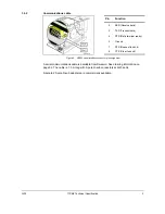
With a Swecoin power supply unit (see ordering information on page 32, and dimensions
drawing on page 26), just connect the cable from the power supply to control board con-
nector J5.
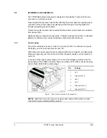
If you use another type of power supply unit, connect the voltages according to the fol-
lowing table. At the TTPM2 end of the cable, use a Molex 22-01-2065 connector housing,
and six Molex 08-50-0032 contact springs:
Pin Voltage
1 +5
V
2
Ground (for 5 V)
3 +24
V
4 +24
V
5
Ground (for 24 V)
6
Ground (for 24 V)
Figure 5. Power supply connector J5 pin assignment
NOTE! –
Both the 5 V and 24 V ground, as well as the chassis of the printer, must be
connected to ground potential (safety ground).
8
TTPM2 Technical Specification
0309


