Engine General Information and Diagnosis: 1A-40
Step
Action
Yes
No
1
1) Turn the ignition switch OFF.
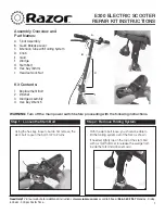
2) Remove the front frame cover. (Refer to “Front Frame
Cover Removal and Installation in Section 9D (Page9D-
17)”.)
3) Check the IAT sensor coupler for loose or poor contacts.
If OK, then measure the IAT sensor voltage at the wire
side coupler.
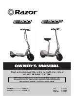
4) Disconnect the coupler (1) and turn the ignition switch
ON.
5) Measure the voltage between B/Bl wire terminal and
ground.
6) If OK, then measure the voltage between B/Bl wire
terminal and B/Br wire terminal.
IAT sensor voltage
4.5 – 5.5 V
(Positive terminal: B/Bl – Negative terminal: Ground,
Positive terminal: B/Bl – Negative terminal: B/Br)
Special tool
(A): 09900–25008 (Multi-circuit tester set)
Tester knob indication
Voltage (
)
Is the voltage OK?
Go to Step 2.
• Loose or poor
contacts on the ECM
coupler (terminal (25)
and (4)). Refer to
“Terminal Alignment
of ECM Coupler
(Harness Side)
(Page1A-5)”.
• Open or short circuit
in the B/Bl wire or B/
Br wire.
1
I705H1110025-02
V
B/Bl
B/Br
(A)
I705H1110026-03
Содержание Burgman AN400
Страница 1: ...9 9 5 0 0 3 4 1 0 0 0 1 E AN400 ...
Страница 4: ......
Страница 33: ...Maintenance and Lubrication 0B 6 INTAKE SIDE I310G1020024 02 ...
Страница 34: ...0B 7 Maintenance and Lubrication EXHAUST SIDE I310G1020025 02 ...
Страница 58: ...0C 10 Service Data ...
Страница 284: ...1K 6 Exhaust System ...
Страница 340: ...3A 10 Drive Chain Drive Train Drive Shaft ...
Страница 384: ...4D 9 Parking Brake ...
Страница 420: ...6B 13 Steering Handlebar ...
Страница 456: ...9D 9 Exterior Parts 1 2 A I705H1940056 03 1 Pillion rider handle 2 Pillion rider handle cover A To frame ...
Страница 474: ...Prepared by April 2006 Part No 99500 34100 01E Printed in Japan 476 ...
Страница 475: ...Printed in Japan K7 ...