SureCall | 48346 Milmont Drive, Fremont CA 94538 | 1-888-365-6283 | [email protected]
SureCall | 48346 Milmont Drive, Fremont CA 94538 | 1-888-365-6283 | [email protected]
25
24
CHAPTER 5: CONFIGURATION & TESTING
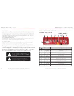
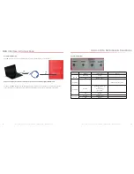
5.1 Powering on the BDA
1. Make sure the exterior and interior antenna cables are firmly connected to their corresponding ports on the
NEMA-4 enclosure.
2. Plug a surge suppressor into a grounded 110VAC wall outlet.
3. Plug the AC end of the power adapter (supplied with your BDA) into the surge suppressor.
4. Plug the DC end of the power adapter into the Power port on the NEMA enclosure.
5. Verify that the green Power light is illuminated.
6. When the booster is turned on, the band lights will flash red and yellow for approximately 10 seconds.
CAUTION: ONLY USE THE POWER SUPPLY INCLUDED
WITH THE BDA. USE OF ANOTHER POWER SUPPLY
COULD DAMAGE THE BDA AND/OR POWER SUPPLY.
CAUTION: DO NOT PROCEED BEYOND THIS POINT
UNTIL THE BDA IS POWERED ON AND NO RED WARNING
LIGHTS ARE ILLUMINATED.
5.2 DIP Switch Configuration
By default, your booster ships with all DIP switches turned OFF, providing maximum gain in all channels
However, BEFORE INITIAL CONFIGURATION, set booster switches with high, but not full, attenuation (as full
attentuation would cause the band to shut off).
DURING CONFUGURATION, you may add gain incrementally until the signal level has improved enough to meet
safety requirements.
Note that red flashing lights indicate the system has detected oscillation for the corresponding channel(s). The band
will turn off (stop working) if adjustments are not made. When adjusting booster attenuation, full power is not always
the best option. The goal is to obtain a signal level througout the building that meets safety requirements.
Configuration and Testing
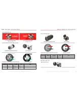
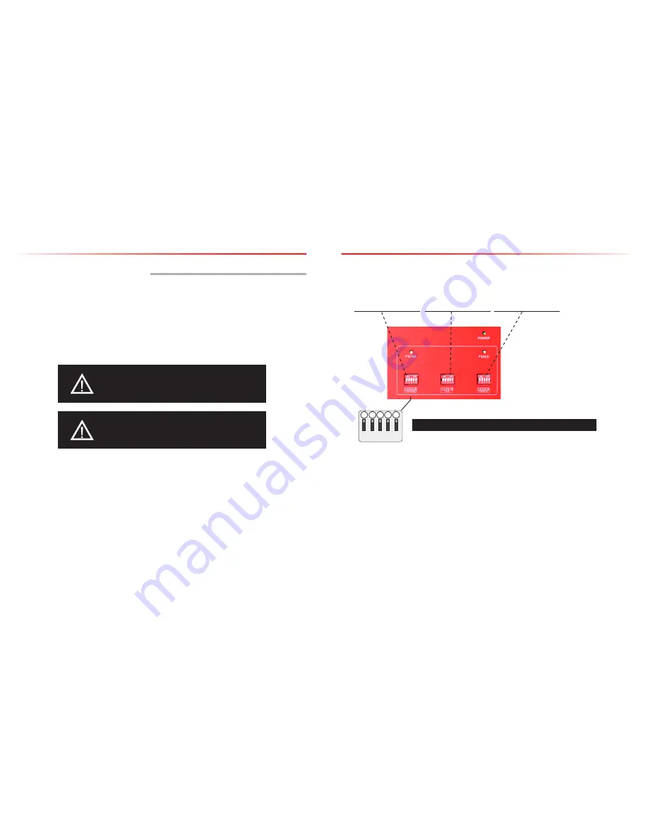
The following diagrams and notes explain how to interpret, and use, these switch banks.
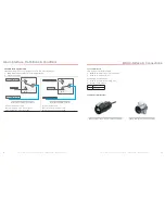
DIP switch organization
PS 700 DL DIP switches
control 700 band
downlink
PS UL DIP switches
control 700 band and 800
band uplink
PS 800 DL DIP switches
control 800 band
downlink
Configuration and Testing
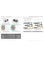
UPLINK
DOWNLINK
1 2 4 8 16
1 2 4 8 16
1 2
3
4
5
PS-UL
PS700-DL
1 2 4 8 16
1 2 4 8 16
1 2 3
4
5
Additive combination effects:
• Switch 1 (1 dB) + Switch 2 (2 dB) = 3 dB attenuation
• Switch 1 (1 dB) + Switch 2 (2 dB) + Switch 3 (4 dB) = 7 dB attenuation
• Switch 1 (1 dB) + Switch 2 (2 dB) + Switch 3 (4 dB) + Switch 4 (8 dB) = 15 dB attenuation
• Switch 1 (1 dB) + Switch 2 (2 dB) + Switch 3 (4 dB) + Switch 4 (8 dB) + Switch 5 (16 dB) = 31 dB attenuation
Switch 1 Switch 2 Switch 3 Switch 4 Switch 5
1 dB 2 dB 4 dB 8 dB 16 dB


