13
12
Hardware Installation
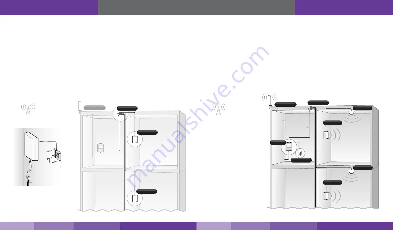
For Each Indoor Panel Antenna:
1.
Choose location for mounting antenna on vertical surface. Ideal height off the ground or floor should be the
approximate height of regular cell phone use.
2.
Using plate, mark position of desired screw placement with pencil or marker.
3.
Screw mounting plate into place with the slide panel protruding towards you.
4. Slide antenna securely onto mounting plate.
5.
Connect antenna’s RF cable to the cable connector of one of the four 75 ft. lengths of SC-400-75-TNC cable
and run along route to planned location of your booster’s 4 way splitter. Note: Should there be an excessive
length of unneeded cable, optional TNC cable crimpers have been provided in order to shorten the cable.
6.
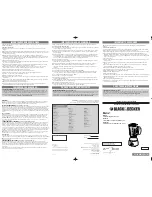
Once all indoor antennas and cables are in place, connect cable runs from indoor antennas to the 4-way
splitter ports. Note: an optional 2-way splitter has been provided if only 2 indoor antennas are being used.
7.
Connect the provided 30 ft. of SC-400 cable to the remaining end of the splitter and route cable to the
planned location of your booster.
Note: Be sure to provide the minimum 50 ft. of separation from outdoor antenna (see table on page 9
).
Hardware Installation
Step 4. Install the Signal Booster
1.
When placing the booster, select a location close to a working AC outlet. Do not expose the signal booster to
excessive heat, direct sunlight, moisture, and airtight enclosures.
2.
If you’d like to mount the booster to a wall, mark location of screw tabs on the wall in the desired location. Use
supplied screws or appropriate screws for surface of mounting location and drill through screw tab holes on
booster.
3.
Connect the outdoor antenna cable to the signal booster connector port marked OUTSIDE and hand-tighten
the connection.
4. Connect the cable coming from the indoor antennas’ 4-way splitter to the booster port marked INSIDE (see
) and hand-tighten the connection.
5. Connect the AC power cord to the signal booster.
6.
Connect the plug on the other end of the 110V AC power outlet.
7. Turn the booster’s power switch on.
Note:
If the Power LED does not turn ON or the Alert LEDs continue to flash, (see
).This booster is rated for 5-20V input voltage. DO NOT use the booster with
a higher voltage power supply. This can damage the booster, cause personal injury and void your warranty.
Outdoor Omni
Outdoor
Cable
(75 ft.)
Indoor Panel
Indoor Panel
4-Way Splitter
Indoor
Cables
(75 ft.)
Indoor
Cable
(30 ft.)
Planned
booster
location
RF CABLE
SC-400
FLAT SURFACE
MOUNTING PLATE
SCREWS
Indoor
Cables
(75 ft.)
Outdoor
Cable
(75 ft.)
Indoor
Cable
(30 ft.)
Indoor Panel
Indoor Panel
Indoor Panel
Option B
4-Way Splitter
Fusion7
Power Supply
Indoor Dome
Option A
Option A
Indoor Panel
Option B
Indoor Dome
Outdoor Omni
Note:
If desired surface for installation plate is wood or concrete, wood or masonry screws for L-plate will have to be purchased separately.
https://www.signalbooster.com | 1-855-846-2654 | [email protected]
https://www.signalbooster.com | 1-855-846-2654 | [email protected]


