


2-18
X7SBL-LN1/LN2 User’s Manual
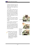
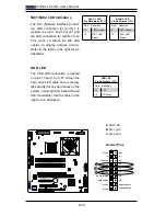
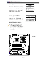
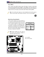
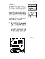
Power LED
The Power LED connector is located
at JLED. This connection is used to
provide LED Indication of power being
supplied to the system. See the table
on the right for pin definitions.
PWR LED
Pin Definitions
Pin# Definition
1
+5V
2
Key
3
Ground
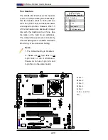
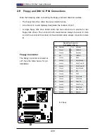
External Speaker/Internal
Buzzer
On the J9 header, pins 1-4 are for an
External Speaker and pins 3-4 are for
the Internal Buzzer See the table on
the right for speaker pin definitions.
Note:
Connect a cable to pins
1-4 to user an external speaker.
If you wish to use the onboard
buzzer, you should close pins 3-4
with a cap.
Speaker Connector
Pin Setting Definition
Pins 3-4
Internal Speaker
Pins 1-4
External Speaker
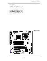
A.
PWR LED
B.
Speaker
B
A
Содержание X7SBL-LN1
Страница 1: ...X7SBL LN1 LN2 USER S MANUAL Revision 1 1a ...
Страница 50: ...2 32 X7SBL LN1 LN2 User s Manual Notes ...
Страница 56: ...3 6 X7SBL LN1 LN2 User s Manual Notes ...
Страница 88: ...A 2 X7SBL LN1 LN2 User s Manual Notes ...
Страница 94: ...C 4 X7SBL LN1 LN2 User s Manual Notes ...


