background image

Chapter 6: Advanced Chassis Setup

6-13

6-9  Power Supply

The SC732 chassis includes a 900 Watt power supply. In the event that it becomes 
necessary to replace the power supply, follow the instructions below.

Changing the Power Supply

1.  Disconnect the chassis from any power source.

2.  Disconnect the motherboard cables.

3.  Remove the screws securing the power supply to the chassis, which are 

located on the rear of the chassis. Set these screws aside for later use.

4.  Gently lift the power supply out of the chassis.

5.  Replace the failed power supply with an identical power supply model.

6.  Secure the new power supply using the screws previously set aside.

7.  Plug the AC power cord back into the module and power-up the system.

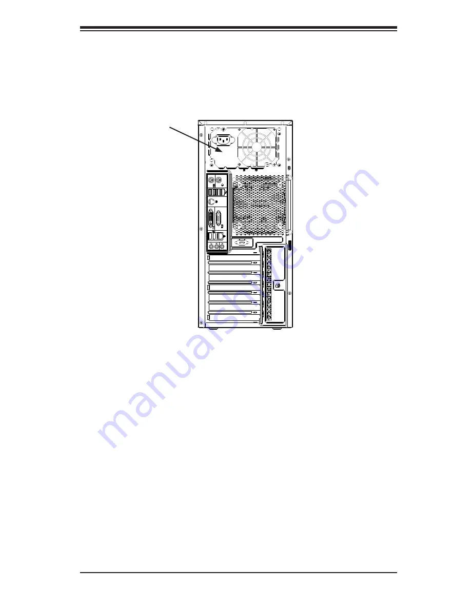
Figure 6-12.  Removing the Power Supply

Power Supply

Содержание SuperWorkstation 7038A-I

Страница 1: ...SuperWorkstation 7038A I SUPER USER S MANUAL 1 0...

Страница 2: ...ny such disputes Super Micro s total liability for all claims will not exceed the price paid for the hardware product FCC Statement This equipment has been tested and found to comply with the limits f...

Страница 3: ...D4 903B chassis Chapter 2 Server Installation This chapter describes the steps necessary to setup the SuperWorkstation 7038A I into a rack and check out the server configuration prior to powering up t...

Страница 4: ...ing the serverboard Chapter 6 Advanced Chassis Setup Refer to Chapter 6 for detailed information on the SC732D4 903B chassis You should follow the procedures given in this chapter when installing remo...

Страница 5: ...v Preface Notes...

Страница 6: ...2 Installation 2 1 Overview 2 1 2 2 Unpacking the System 2 1 2 3 Warnings and Precautions 2 1 2 3 Accessing the Inside of the System 2 2 Chapter 3 System Interface 3 1 Overview 3 1 3 2 Control Panel B...

Страница 7: ...ables 5 2 Connecting the Control Panel 5 2 5 4 I O Ports 5 3 5 5 Processor and Heatsink Installation 5 4 Installing an LGA 2011 Processor 5 4 Installing a CPU Heatsink 5 7 Removing the Heatsink 5 8 5...

Страница 8: ...9 6 7 Installing System Fans 6 10 6 8 Installing the Front Bezel 6 12 6 9 Power Supply 6 13 Chapter 7 BIOS 7 1 Introduction 7 1 Starting BIOS Setup Utility 7 1 How To Change the Configuration Data 7...

Страница 9: ...n included with the SuperWorkstation 7038A I as listed below Two 9 cm PWM SuperQuiet chassis fans FAN 0124L4 Four hot swap drive carriers for SATA drives MCP 220 73101 0B Note For your system to work...

Страница 10: ...com Memory The X10DAi has 16 DIMM slots that can support up to 1024 GB of RDIMM Reg istered DIMMs or LRDIMM Load Reduced DIMMs ECC DDR4 2133 1866 1600 memory See Chapter 5 for details SATA A SATA con...

Страница 11: ...d to support eight SATA hard drives Front Control Panel The control panel on the SuperWorkstation 7038A I includes system monitoring LEDs a main power button and a system reset button In addition two...

Страница 12: ...HEADER USB 2 0 USB BIOS HEADER SPI 3 4 SLOT1 1333 2133 1333 2133 DDRIV P1 P1 P0 P0 2 1 DDRIV 1 4 1 3 1 2 1 1 QPI 9 6G SLOT3 PCI E X16 G3 DMI2 PCI E X16 PCI E X16 G3 1 5 1 6 PCI E X8 G3 DMI2 DMI2 DDR I...

Страница 13: ...e Address Super Micro Computer B V Het Sterrenbeeld 28 5215 ML s Hertogenbosch The Netherlands Tel 31 0 73 6400390 Fax 31 0 73 6416525 Email sales supermicro nl General Information support supermicro...

Страница 14: ...SuperWorkstation 7038A I User s Manual 1 6 Notes...

Страница 15: ...you should file a damage claim with the carrier who delivered it Decide on a suitable location for the SuperWorkstation It should be situated in a clean dust free area that is well ventilated Avoid a...

Страница 16: ...sis interior Removing the Side Covers 1 Disconnect the chassis from any power souce 2 Remove the two screws securing the left side cover to the chassis 3 Slide the left cover toward the rear of the ch...

Страница 17: ...gle push button is located on the front of the chassis Power 3 3 Communications Panel Components The SC732D4 features a front communication panel allowing easy access to the chassis communication port...

Страница 18: ...s when flashing 3 4 Control Panel LEDs The control panel located on the front of the SC732 chassis has three LEDs These LEDs provide you with critical information related to different parts of the sys...

Страница 19: ...apter 5 This LED will remain flashing or on as long as the indicated condition exists 3 5 Drive Carrier LEDs Note the LEDs of some drive carriers may not function depending on the number of drives tha...

Страница 20: ...3 4 SuperWorkstation 7038A I User s Manual Notes...

Страница 21: ...nt for assistance Only certified technicians should attempt to install or configure components Read this appendix in its entirety before installing or configuring components in the Supermicro chassis...

Страница 22: ...considere los riesgos de la corriente el ctrica y familiar cese con los procedimientos est ndar de prevenci n de accidentes Al final de cada advertencia encontrar el n mero que le ayudar a encontrar...

Страница 23: ...l kan veroorzaken Voordat u aan enige apparatuur gaat werken dient u zich bewust te zijn van de bij een elektrische installatie betrokken risico s en dient u op de hoogte te zijn van de standaard proc...

Страница 24: ...ie en des Systems an die Stromquelle die Installationsanweisungen lesen Advertencia Lea las instrucciones de instalaci n antes de conectar el sistema a la red de alimentaci n Attention Avant de branch...

Страница 25: ...rt ist Stellen Sie sicher dass der Nennwert der Schutzvorrichtung nicht mehr als 250 V 20 A betr gt Advertencia Este equipo utiliza el sistema de protecci n contra cortocircuitos o sobrecorrientes del...

Страница 26: ...eift um Systemsbestandteile anzubringen oder zu entfernen Warning The system must be disconnected from all sources of power and the power cord removed from the power supply module s before accessing t...

Страница 27: ...nentes de sistema Attention Le syst me doit tre d branch de toutes les sources de puissance ainsi que de son cordon d alimentation secteur avant d acc der l int rieur du chassis pour installer ou enle...

Страница 28: ...arnung Das Installieren Ersetzen oder Bedienen dieser Ausr stung sollte nur geschultem qualifiziertem Personal gestattet werden Advertencia Solamente el personal calificado debe instalar reemplazar o...

Страница 29: ...stallation in Bereichen mit beschr nktem Zutritt vorgesehen Der Zutritt zu derartigen Bereichen ist nur mit einem Spezialwerkzeug Schloss und Schl ssel oder einer sonstigen Sicherheitsvorkehrung m gli...

Страница 30: ...ame or equivalent type recommended by the manufacturer Dispose of used batteries according to the manufacturer s instructions Waarschuwing Dit apparaat is bedoeld voor installatie in gebieden met een...

Страница 31: ...ecommand e par le fabricant Jeter les piles usag es conform ment aux instructions du fabricant Advertencia Existe peligro de explosi n si la bater a se reemplaza de manera incorrecta Reemplazar la bat...

Страница 32: ...para fuentes de alimentaci n Para cortar por completo el suministro de energ a deben desconectarse todas las conexiones Attention Cette unit peut avoir plus d une connexion d alimentation Pour suppri...

Страница 33: ...ero es peligroso Tenga cuidado cuando lo revise Attention Lorsque le syst me est en fonctionnement des tensions lectriques circulent sur le fond de panier Prendre des pr cautions lors de la maintenanc...

Страница 34: ...lectrical codes Warnung Die Installation der Ger te muss den Sicherheitsstandards entsprechen Advertencia La instalacion del equipo debe cumplir con las normas de electricidad locales y nacionales Bac...

Страница 35: ...ional laws and regulations Attention L quipement doit tre install conform ment aux normes lectriques nationales et locales Waarschuwing Bij installatie van de apparatuur moet worden voldaan aan de lok...

Страница 36: ...seguir todas las leyes y reglamentos nacionales Attention La mise au rebut ou le recyclage de ce produit sont g n ralement soumis des lois et ou directives de respect de l environnement Renseignez vo...

Страница 37: ...dedos los destornilladores y todos los objetos lejos de las aberturas del ventilador Attention Il est possible que les ventilateurs soient toujours en rotation lorsque vous retirerez le bloc ventilat...

Страница 38: ...Adapter kann zu einer Fehlfunktion oder ein Brand entstehen Elektrische Ger te und Material Safety Law verbietet die Verwendung von UL oder CSA zertifizierte Kabel UL oder CSA auf der Code f r alle an...

Страница 39: ...utres appareils lectriques que les produits d sign s par Supermicro seulement AC AC UL CSA UL CSA UL CSA Supermicro UL CSA AC Electrical Appliance and Material Safety Law UL CSA UL CSA Waarschuwing Bi...

Страница 40: ...4 20 SuperWorkstation 7038A I User s Manual Notes...

Страница 41: ...to handle them very carefully see previous chapter To prevent the serverboard from bending keep one hand under the center of the board to support it when handling The following measures are generally...

Страница 42: ...s with their locations noted should be connected See the layout on page 5 9 for connector locations SATA drive data cables I SATA0 I SATA7 Control Panel cable JF1 SGPIO cable T SGPIO1 T SGPIO2 Importa...

Страница 43: ...2 0 8 Line In 2 USB0 Port USB 2 0 9 Line Out 3 USB6 Port USB 3 0 10 Mic In 4 USB5 Port USB 3 0 11 LAN1 Port 5 CEN LFE Out 12 LAN2 Port 6 Surround Out 13 USB8 Port USB 3 0 7 SPDIF Out 14 USB7 Port USB...

Страница 44: ...sink only Make sure to install the serverboard into the chassis before you install the CPU heatsinks When receiving a serverboard without a processor pre installed make sure that the plastic CPU socke...

Страница 45: ...remove the WARNING plastic cap from the socket 5 Use your thumb and index finger to hold the CPU by its edges Align the CPU keys which are semi circle cutouts against the socket keys 6 Once they are a...

Страница 46: ...d plate again and double check that the CPU is aligned properly 7 With the CPU in the socket in spect the four corners of the CPU to make sure that they are flush with the socket 8 Close the load plat...

Страница 47: ...Place the heatsink on top of the CPU so that the four mounting holes are aligned with those on the serverboard and the heatsink bracket underneath 3 Screw in two diagonal screws i e the 1 and the 2 sc...

Страница 48: ...e heatsink screws from the serverboard in the sequence as shown in the illustration below 2 Gently wriggle the heatsink to loosen it from the CPU Do not use excessive force when wriggling the heatsink...

Страница 49: ...page 2 Press down the release tabs on the ends of a memory slot Insert each DIMM vertically into its slot Pay attention to the notch along the bottom of the mod ule to prevent inserting the DIMM incor...

Страница 50: ...DIMMC1 P1 DIMMD1 P2 DIMME1 P2 DIMMF1 P2 DIMMG1 P2 DIMMH1 2 CPUs 10 16 DIMMs CPU1 CPU2 P1 DIMMA1 P1 DIMMB1 P1 DIMMC1 P1 DIMMD1 P2 DIMME1 P2 DIMMF1 P2 DIMMG1 P2 DIMMH1 Any memory pairs in P1 P2 DIMM sl...

Страница 51: ...removing the PCI slot shield for the slot you wish to populate 2 Fully seat the card into the card slot pushing down with your thumbs evenly on both sides of the card 3 Finish by using a screw to secu...

Страница 52: ...SGPIO2 JTPM1 JSD2 JSD1 JL1 JSPDIF_IN1 JSPDIF_OUT1 JD1 JPP1 JPP0 JS5 JPWR2 JPWR1 JPI2C1 JTBT1 JS2 JS6 BIOS LICENSE MAC CODE BAR CODE USB0 1 AUDIO_FP I SATA5 MDIO SAS4 7 USB9 10 3 0 USB7 8 3 0 TPM PORT...

Страница 53: ...CPU2 is installed PCH Slot6 PCI E 2 0 x4 in x8 Slot FAN1 7 FANA CPU System Fan Headers J24 ATX 24 Pin Power Connector JD1 Speaker Power LED Indicator JF1 Front Panel Control Header JL1 Chassis Intrusi...

Страница 54: ...onnector J24 meets the SSI EPS 12V speci fication Refer to the table on the right for the pin definitions of the ATX 24 pin power connector You must also con nect the 8 pin power connectors to your po...

Страница 55: ...cable to display network activity See the table for pin definitions OH Fan Fail Indicator Status State Definition Off Normal On Overheat Flash ing Fan Fail Power On LED The Power On LED connector is l...

Страница 56: ...mper Speaker Connector Pin Settings Pin Setting Definition Pins 4 7 External Speaker Pins 6 7 Internal Speaker Internal Speaker The Internal Speaker located at SP1 can be used to provide audible indic...

Страница 57: ...UN X 19 LPCPD 20 LDRQ X Standby Power Header The Standby Power header is located at STBY1 on the serverboard See the table on the right for pin definitions Standby Power Pin Definitions Pin Definition...

Страница 58: ...h Definition Audio This serverboard features a 7 1 Channel High Definition Audio HDA codec that provides 8 DAC channels The HD audio supports multiple streaming 7 1 sound playback through the frontpan...

Страница 59: ...SB2 3 support USB 2 0 and USB9 10 support USB 3 0 connections In addition a Type A USB header USB4 also provides a USB 2 0 connection USB cables are not included for front access See the tables on the...

Страница 60: ...jumper is on both pins and Open means the jumper is either on only one pin or completely removed Connector Pins Jumper Setting 3 2 1 3 2 1 CMOS Clear JBT1 is used to clear CMOS which will also clear a...

Страница 61: ...l generate a non maskable interrupt signal for the application that hangs See the table on the right for jumper settings Watch Dog must also be enabled in BIOS Watch Dog Jumper Settings Jumper Setting...

Страница 62: ...erverboard When this LED is on the system is on Be sure to turn off the system and unplug the power cord before removing or install ing components See the table at right for more information Onboard P...

Страница 63: ...site at http www supermicro com products Find the product page for your serverboard here where you may down load individual drivers and utilities After creating a CD DVD with the ISO files insert the...

Страница 64: ...ent versions and can be used with Nagios to maximize your system monitoring needs With SuperDoctor 5 Man agement Server SSM Server you can remotely control power on off and reset chassis intrusion for...

Страница 65: ...y in any way a damaged battery may release hazardous materials into the environment Do not discard a used battery in the garbage or a public landfill Please comply with the regulations set up by your...

Страница 66: ...5 26 SuperWorkstation 7038A I User s Manual Notes...

Страница 67: ...following measures are generally sufficient to protect your equipment from static discharge Precautions Use a grounded wrist strap designed to prevent static discharge Touch a grounded metal object b...

Страница 68: ...ssis 3 Slide the left cover toward the rear of the chassis 4 Lift the left cover from the chassis 5 Remove the three screws securing the right side cover to the chassis 6 Slide the right cover toward...

Страница 69: ...omponents in the chassis interior it is necessary to rotate the hard drive cage B This will provide sufficient room to install and configure the chassis components Rotating the Hard Drive Cage 1 Disco...

Страница 70: ...nnect the chassis from any power source 2 Rotate the hard drive cage outward 90 degrees as described in section 6 3 3 Disconnect all of the cables from the hard drive 4 Press the release tab on the si...

Страница 71: ...liding it towards the back of the the hard drive cage until it clicks into a locked position 10 If desired each hard drive carrier may be secured to the exterior of the hard drive cage using one optio...

Страница 72: ...6 6 SuperWorkstation 7038A I User s Manual Figure 6 5 Installing a Hard Drive Carrier into the Hard Drive Cage 1 11 1 9 Optional Screw...

Страница 73: ...chassis must be powered down before hard drives can be removed from the hard drive carriers Removing and Installing 2 5 Hard Drives 1 Disconnect the chassis from any power source 2 Loosen the thumb s...

Страница 74: ...ier 7 Insert the new hard drive into the hard drive carrier 8 Insert the hard drive carrier into the hard drive cage sliding it towards the back of the the hard drive cage until it clicks into a locke...

Страница 75: ...from the bottom and pulling off the front of the chassis 2 Remove the cover plate from the 3 5 device slot on the front of the chassis 3 Install the bracket rail A onto one side of the 3 5 device by...

Страница 76: ...to the chassis 2 Insert the four rubber pins through mounting holes in the rear of the chassis and through the mounting holes in the rear fan 3 Pull the rubber pins through the mounting holes of the f...

Страница 77: ...oles in the front fan 3 Pull the rubber pins through the mounting holes of the system fan to secure the fan to the chassis 4 Lower the fan into the chassis aligning the holes at the top of the front f...

Страница 78: ...ezel Front Bezel Installation 1 Insert the tabs on the front bezel into the mounting holse on the front of the chassis 2 Ensure that the cover fits snugly This completes the installation of basic comp...

Страница 79: ...onnect the motherboard cables 3 Remove the screws securing the power supply to the chassis which are located on the rear of the chassis Set these screws aside for later use 4 Gently lift the power sup...

Страница 80: ...6 14 SuperWorkstation 7038A I User s Manual Notes...

Страница 81: ...t options cannot be configured Options in blue can be configured by the user The right frame displays the key legend Above the key legend is an area reserved for a text message When an option is selec...

Страница 82: ...tem has a BIOS related issue Flashing the wrong BIOS can cause irreparable damage to the system In no event shall Supermicro be liable for direct indirect special incidental or consequential damages a...

Страница 83: ...MM DD YYYY format The time is entered in HH MM SS format Note The time is in the 24 hour format For example 5 30 P M appears as 17 30 00 Supermicro X10DAi C Version This item displays the version of t...

Страница 84: ...EM logo at bootup Select Disabled to display the POST messages Select Enabled to display the OEM logo instead of the normal POST messages The options are Enabled and Disabled AddOn ROM Display Mode Us...

Страница 85: ...ce after its initial boot failure The options are Disabled Legacy Boot and EFI Boot Power Configuration EuP Select Enabled for EuP Energy using Product support to conserve energy use and enhance power...

Страница 86: ...caused by the components whenever needed The options are Disabled and Enabled Hyper Threading All Select Enable to support Intel s Hyper threading Technology to enhance CPU per formance The options a...

Страница 87: ...oot the system for changes on this setting to take effect Please refer to Intel s website for detailed information DCU Data Cache Unit Streamer Prefetcher Available when supported by the CPU If set to...

Страница 88: ...system performance Select Disabled to disable power saving settings The options are Disable Energy Efficient and Custom If the option is set to Custom the following items will display CPU P State Cont...

Страница 89: ...le to allow the BIOS to report the CPU C6 state ACPI C3 to the operating system During the CPU C6 state power to all cache is turned off The options are Enable and Disable Enhanced Halt State C1E Sele...

Страница 90: ...m to configure the link speed of a PCI E device installed on the PCI E slot specified by the user The options are Gen1 2 5 GT s Gen2 5 GT s Gen3 8 GT s and Auto IIO1 Port 2A Link Speed Use this item t...

Страница 91: ...for each CB device The options are Disable and Enable Relaxed Ordering Select Enable to enable Relaxed Ordering support which will allow certain transactions to violate the strict ordering rules of PC...

Страница 92: ...display Number of CPU Number of IIO Current QPI Link Speed Current QPI Link Frequency QPI Global MMIO Low Base Limit QPI Global MMIO High Base Limit QPI PCIe Configuration Base Size Link Frequency Sel...

Страница 93: ...Select Enabled to enable data scrambling to enhance system performance and data integrity The options are Auto Disabled and Enabled DRAM RAPL Running Average Power Limit Baseline Use this feature to...

Страница 94: ...s a process that allows the CPU to correct correctable memory errors detected on a memory module and send the correction to the requestor the original source When this item is set to Enable the PCH Pl...

Страница 95: ...e should be claimed by the XHCI driver The settings are Enabled and Disabled EHCI Enhanced Host Controller Interface Hand Off This item is for operating systems that do not support Enhanced Host Contr...

Страница 96: ...d for EHCI support The options are Disabled and Enabled Azalia Select Enabled to enable onboard Azalia audio devices Select Auto for the BOIS to automatically enable Azalia support when an onboard Aza...

Страница 97: ...tem is set to Enabled the SATA AHCI controller manages the power usage of the SATA link The controller will put the link to a low power state when the I O is inactive for an extended period of time an...

Страница 98: ...extended period of time and the power state will return to normal when the I O becomes active The options are Enabled and Disabled SATA RAID Option ROM UEFI Driver Select EFI to load the EFI driver f...

Страница 99: ...are Enabled and Disabled Configure sSATA as Select IDE to configure an sSATA drive specified by the user as an IDE drive Select AHCI to configure an sSATA drive specified by the user as an AHCI drive...

Страница 100: ...re Hard Disk Drive and Solid State Drive If the item above Configure sSATA as is set to RAID the following items will display Support Aggressive Link Power Management When this item is set to Enabled...

Страница 101: ...sSATA Port 0 Port 3 Spin Up Device On an edge detect from 0 to 1 set this item to allow the PCH to start a COMRE SET initialization to the device The options are Enabled and Disabled Port 0 Port 3 sSA...

Страница 102: ...abled and Disabled PCI SERR Support Select Enabled for the BIOS to generate a SERR number when a runtime SERR System Error event occurs on a PCI PCI E slot for SERR reporting The options are Enabled a...

Страница 103: ...MMIO High Size Use this item to select the high memory size according to memory address mapping for the PCH The options are 256G 128G 512G and 1024G PCI Devices Option ROM Setting CPU1 Slot 1 PCI E x1...

Страница 104: ...e TPM state to take effect The options are Disabled and Enabled Pending Operation Use this item to schedule a TPM related operation to be performed by a security device for system data integrity Your...

Страница 105: ...ystem performance The options are Enabled and Disabled ACPI Sleep State This feature selects the ACPI Sleep State that the system will enter into when the suspend button is activated The options are S...

Страница 106: ...mponent or disk drive without shutting down the system The options are Enabled and Disabled Intel Thunderbolt Technology Select Enabled to support Intel Thunderbolt Technology to enhance system perfor...

Страница 107: ...low a PCI E device used in the Thunderbolt technology to be detected by the BIOS before system boot The default setting is 0 Disabled TBT Device IO Resource Support Select Enabled to allocate IO resou...

Страница 108: ...abled Runtime Error Logging Support Select Enabled to support Runtime Error Logging The options are Enabled and Disabled If this item is set to Enabled the following item will be available for configu...

Страница 109: ...e Immediately SMBIOS Event Log Standard Settings Log System Boot Event Select Enabled to log system boot events The options are Disabled and Enabled MECI Multiple Event Count Increment Enter the incre...

Страница 110: ...se this feature to set the administrator password which is required before the user entering the BIOS setup utility The length of the password should be from 3 characters to 20 characters long User Pa...

Страница 111: ...or system boot The options are Legacy UEFI and Dual Fixed Boot Order Priorities This option prioritizes the order of bootable devices from which the system will boot Press Enter on each entry from top...

Страница 112: ...the boot priority list Path for Boot Option Select the device path the file system for the new boot device to use Create After selecting a boot device to add and the path for this new device choose t...

Страница 113: ...Chapter 7 BIOS 7 33 UEFI Application Boot Priorities UEFI Boot Order 1...

Страница 114: ...Save Changes and Reset When you have completed the system configuration changes select this option to leave the BIOS setup utility and reboot the computer for the new system configura tion parameters...

Страница 115: ...Defaults from the Exit menu and press En ter This enables the user to save any changes to the BIOS setup for future use Restore User Defaults To set this feature select Restore User Defaults from the...

Страница 116: ...7 36 SuperWorkstation 7038A I User s Manual Notes...

Страница 117: ...ould consult with your system manufacturer for possible repairs These fatal errors are usually communicated through a series of audible beeps The numbers on the fatal error list correspond to the numb...

Страница 118: ...A 2 SuperWorkstation 7038A I User s Manual Notes...

Страница 119: ...Sixteen DIMM sockets supporting up to 1024 GB of DDR4 2133 1866 1600 RDIMMs or LRDIMMs Note See the memory section in Chapter 5 for details SATA Controller Intel on chip controller for ten port SATA 3...

Страница 120: ...Part PWS 903 PQ Rated Output Voltages 3 3V 25A 5V 25A 12VALL 100A 12V 0 5A 5Vsb 4A Operating Environment Operating Temperature 10 to 35 C 50 to 95 F Non operating Temperature 40 to 70 C 40 to 158 F O...

Страница 121: ...anagement Practices Regulations for Perchlorate Materials This Perchlorate warning applies only to products containing CR Manganese Dioxide Lithium coin cells Perchlorate Material special handling may...

Страница 122: ...erform be reasonably expected to result in significant injury or loss of life or catastrophic property damage Accordingly Supermicro dis claims any and all liability and should buyer use or sell such...

Отзывы: